Blog
All
Process Presentation

All

How Should LSR Overmolded Smart Glasses Temple Tips Be Designed for Comfort and Retention?

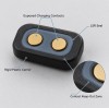
LSR overmolded smart glasses temple tips should provide soft ear contact, anti-slip grip and stable retention without covering hinges, speakers, charging contacts, sensors or other functional areas. Reliable design requires controlled silicone coverage, smooth edge transitions, suitable hardness and thickness, stable insert positioning, bonding or mechanical retention, and validation on the final eyewear assembly.

Aug 20,2026

How Should LSR Overmolded Smart Glasses Temple Tips Be Designed for Comfort and Retention?

Why Do LSR Overmolded Electronic Housing Gaskets Leak at Corners?

Corner leakage in an LSR overmolded electronic housing gasket is usually caused by uneven compression, abrupt sealing-path geometry, housing warpage, local tolerance stack-up, unstable parting-line or shut-off conditions, or an unsupported silicone corner. Reliable design requires a continuous sealing path, controlled corner transition, stable plastic support and validation on the final assembled housing.

Aug 19,2026

Why Do LSR Overmolded Electronic Housing Gaskets Leak at Corners?

How Should an LSR Sealing Collar Be Designed Around EV Charging Inlet Terminals?

An LSR sealing collar around an EV charging inlet terminal should seal the terminal-to-housing interface while keeping the electrical mating contact completely exposed. Reliable design depends on silicone coverage position, collar geometry, terminal centering, housing interference, metal surface condition, mold shut-off and tolerance stack-up. The final structure should be validated in the actual charging-inlet housing rather than only as a loose overmolded terminal.

Aug 18,2026

How Should an LSR Sealing Collar Be Designed Around EV Charging Inlet Terminals?

How Should Multi-Lip Silicone Seals Be Designed for LSR Overmolded Automotive Connectors?

Multi-lip silicone seals use several controlled sealing ribs to create multiple contact bands between an LSR overmolded automotive connector and its mating housing. Reliable design depends on rib height, width, spacing, root radius, silicone hardness, compression direction, mating-surface tolerance and assembly stop. The complete seal should be validated under minimum, nominal and maximum compression conditions before mass production.

Aug 17,2026

How Should Multi-Lip Silicone Seals Be Designed for LSR Overmolded Automotive Connectors?

How Should No-Silicone Zones Be Designed in LSR Overmolding?

No-silicone zones should be defined as dimensioned functional areas that must remain completely exposed after LSR overmolding. Reliable control requires stable datums, a defined silicone boundary tolerance, supported insert surfaces, precise mold shut-off, controlled gate and parting-line locations, and repeatable inspection. These zones are especially important around terminals, threads, connector openings, FPC pads, sensor windows and assembly datums.

Aug 14,2026

How Should No-Silicone Zones Be Designed in LSR Overmolding?

How Should Metal Inserts Be Prepared Before LSR Overmolding?

Metal inserts should be controlled for material grade, plating, oxidation, oil, contamination, dimensional stability and bonding requirements before LSR overmolding. A visually clean metal surface does not automatically guarantee stable silicone adhesion. Reliable production requires a defined incoming surface condition, validated bonding strategy, protected functional areas, mechanical retention where needed and repeatable insert handling from sampling through mass production.

Aug 13,2026

How Should Metal Inserts Be Prepared Before LSR Overmolding?

Where Should the Gate Be Placed in LSR Overmolding Around Inserts?

Gate location in LSR overmolding determines how silicone reaches the insert, where flow fronts meet and where trapped air is pushed. A poor gate position may move the insert, create weld lines, increase flash or leave thin features incompletely filled. Reliable gate design should consider insert support, wall thickness, sealing areas, flow length, venting and the final fill location before tooling.

Aug 12,2026

Where Should the Gate Be Placed in LSR Overmolding Around Inserts?

How Should Compression Stops Be Designed for LSR Overmolded Seals?

A compression stop limits how far an LSR overmolded seal can be squeezed after assembly. Without a controlled hard stop, screw force, housing tolerance or operator variation may create under-compression or over-compression. Reliable sealing requires the compression stop, silicone lip geometry, hardness, mating gap, insert tolerance and final assembly to be designed and validated as one system.

Aug 11,2026

How Should Compression Stops Be Designed for LSR Overmolded Seals?

How Should Wall Thickness Be Designed for LSR Overmolding?

LSR overmolding wall thickness should be designed according to product function, silicone hardness, flow length, insert support, sealing requirements and demolding conditions. Sections that are too thin may short-shot, tear or lose sealing stability, while unnecessarily thick areas can increase curing time, material use and dimensional variation. Smooth thickness transitions and DFM validation are more important than applying one universal wall-thickness value.

Aug 10,2026

How Should Wall Thickness Be Designed for LSR Overmolding?

Where Should the Mold Parting Line Be Placed on LSR Overmolded Seals?

The mold parting line on an LSR overmolded seal should be placed away from the primary sealing contact surface whenever possible. A poorly positioned parting line can create flash, mismatch, local steps or trimming damage that affects seal compression and leakage performance. Parting-line design should be reviewed together with seal geometry, insert tolerance, mold shut-off, venting, demolding and final assembly conditions before tooling.

Aug 8,2026

Where Should the Mold Parting Line Be Placed on LSR Overmolded Seals?

When Does LSR Overmolding Need Mechanical Retention?

Mechanical retention should be added to LSR overmolding when chemical adhesion alone cannot provide enough protection against peeling, pulling, vibration, thermal cycling or material variation. Through-holes, grooves, undercuts and edge wraparound can create a physical lock between silicone and the insert. The retention structure must be designed together with silicone flow, venting, insert support and demolding.

Aug 7,2026

When Does LSR Overmolding Need Mechanical Retention?

How Should Dimensional Tolerances Be Defined for Flexible LSR Overmolded Parts?

Dimensional tolerances for flexible LSR overmolded parts should be defined according to product function, measurement condition, datum, inspection force, temperature and assembly state. Soft silicone can deform during measurement, so repeated results may differ even when the molded part is stable. Buyers and manufacturers should agree on critical dimensions, inspection fixtures and cavity-specific acceptance criteria before mass production.

Aug 6,2026

How Should Dimensional Tolerances Be Defined for Flexible LSR Overmolded Parts?

How Should Cosmetic Acceptance Standards Be Defined for LSR Overmolded Parts?

Cosmetic acceptance standards for LSR overmolded parts should define viewing conditions, inspection distance, cosmetic zones, defect categories, allowable size and quantity, functional no-defect areas and approved boundary samples. General descriptions such as “good appearance” or “no visible defects” are not sufficient for mass production. Buyers and manufacturers should agree on measurable standards before sample approval.

Aug 5,2026

How Should Cosmetic Acceptance Standards Be Defined for LSR Overmolded Parts?

How Do You Choose the Right Silicone Hardness for LSR Overmolding?

The correct silicone hardness for LSR overmolding depends on sealing compression, wall thickness, flexibility, assembly force, tear risk, demolding and application temperature. A softer silicone is not always better for sealing, and a harder silicone is not always more durable. Hardness, geometry and the substrate structure must be evaluated together through DFM, prototype molding and application-specific testing.

Aug 4,2026

How Do You Choose the Right Silicone Hardness for LSR Overmolding?