Why Do LSR Overmolded Smartwatch Strap Ends Tear Around Metal Inserts?
- Share
- publisher
- SiliconePlus Engineering Team
- Issue Time
- Aug 26,2026
Summary
LSR overmolded smartwatch strap ends can tear or pull away around metal inserts when silicone becomes too thin at the rigid-to-soft transition, metal edges concentrate stress, insert position varies or repeated bending loads the interface in peel rather than pure tension. Reliable design requires controlled wall thickness, supported transitions, appropriate retention and validation under realistic pull and flex conditions.
Answer Excerpt
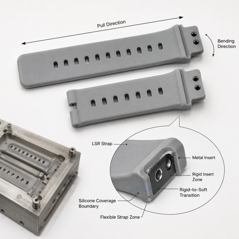
LSR overmolded smartwatch strap ends can tear around metal inserts when repeated bending, pulling and twisting loads become concentrated at the rigid-to-soft transition. The risk increases when silicone becomes too thin near the insert edge, the metal support ends abruptly, the insert shifts during molding or the interface relies on a bonding area that is poorly aligned with the real load direction. Reliable design requires controlled wall thickness, supported transitions and an appropriate bonding or mechanical-retention strategy.
A smartwatch strap is flexible through most of its length, but the connector end often contains a much more rigid structural feature.
This creates an unavoidable change in stiffness.
The flexible silicone strap must transfer load into the rigid metal insert every time the watch is worn, removed, adjusted or accidentally pulled.
The most critical location is therefore often not the center of the strap.
It is the area immediately surrounding the end of the metal insert.
If the geometry changes abruptly, repeated bending may concentrate peel and shear stress at one narrow silicone boundary.
A part may pass an initial straight pull test and still develop cracking or edge lifting after repeated flexing.
For this reason, material compatibility and interface design should be reviewed together before tooling.
Why Is the Area Around the Metal Insert More Vulnerable?
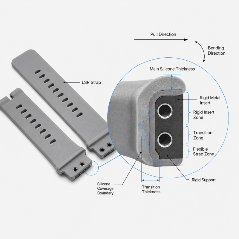
The metal insert and the silicone strap respond very differently to the same external load.
The metal section remains relatively rigid.
The LSR section can stretch, bend and twist.
At the transition between them, the load must move from a flexible elastomer into a much stiffer structure.
This can create:
• Peel stress
• Shear stress
• Local stretching
• Bending concentration
• Twisting around the insert edge
• Repeated compression on one side of the strap
The exact failure mode depends on how the watch strap is loaded.
A straight pull mainly loads the strap along its length.
Normal wearing can be more complex because the strap bends around the wrist while the connector end remains constrained by the watch attachment.
A sudden side pull can introduce both bending and twisting.
The interface should therefore be designed for the real load path rather than only for one simple laboratory pull direction.
How Can the Metal Insert Edge Create a Stress Concentration?
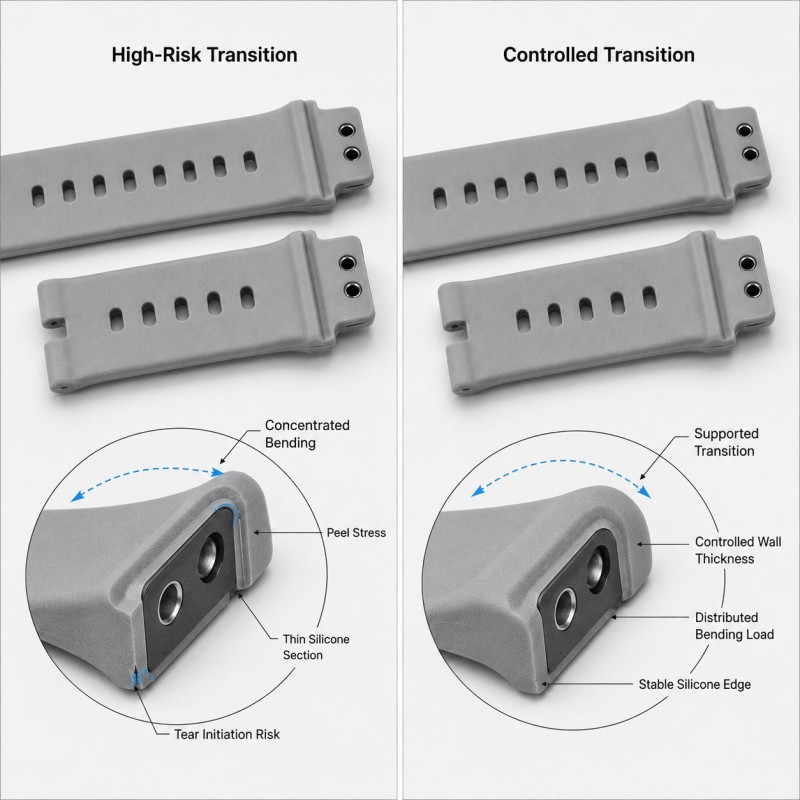
An abrupt metal edge can concentrate deformation in the silicone immediately next to it.
If the rigid insert ends with a sharp step while the surrounding LSR continues into a flexible strap, the silicone may repeatedly bend around the same narrow location.
High-risk conditions can include:
• Sharp insert edges
• Abrupt insert termination
• Very thin silicone over the insert end
• Insufficient silicone around the transition
• A narrow bonding region
• Uneven metal thickness
• Burrs or damaged insert edges
The objective is not to make every hidden metal edge extremely rounded without considering the real product.
Instead, the insert termination, silicone thickness and bending direction should be reviewed together.
Where the design permits it, a supported transition is generally more stable than a structure where flexible silicone begins directly at a sharp unsupported metal edge.
Incoming metal parts should also be inspected for burrs, contamination and dimensional variation before overmolding.
How Should Silicone Wall Thickness Change Around the Insert?
The silicone around the end of the metal insert should remain thick enough to mold consistently and resist repeated flexing.
A very thin local section may create several risks:
• Incomplete filling
• Local tearing
• Greater sensitivity to insert position
• Difficult demolding
• Reduced durability during flexing
• Cosmetic variation
However, simply making the transition extremely thick is not automatically better.
Excessive local thickness can create:
• A bulky strap end
• Uncomfortable wrist contact
• Different local stiffness
• Longer cure or molding sensitivity
• An abrupt transition into the thinner flexible strap
The more useful design approach is to review the complete thickness progression.
The rigid insert zone, transition zone and flexible strap zone should form a controlled structural sequence rather than three unrelated thicknesses.
For broader DFM guidance, review how wall thickness should be designed for LSR overmolding.
When Does the Metal Insert Need Mechanical Retention?
Mechanical retention can provide a physical lock between the metal insert and the cured LSR when the interface experiences significant pulling, peeling or repeated bending.
Possible retention concepts can include:
• Through-holes
• Slots
• Grooves
• Undercuts
• Edge wraparound
• Local retention windows
However, these features should only be used when they match the real insert structure and load direction.
A retention feature should not be added simply because overmolding is being used.
It must also remain compatible with:
• Metal-part strength
• Silicone flow
• Venting
• Local wall thickness
• Insert positioning
• Tool shut-off
• Demolding
The most effective retention structure is one that resists the actual failure direction.
For example, a feature that performs well under straight pull may provide less benefit if the real failure begins as peeling at the insert edge.
For detailed guidance, review when LSR overmolding needs mechanical retention.
Why Is Bending Direction as Important as Pull Strength?
A straight pull test measures only one loading condition.
A smartwatch strap normally experiences several.
During use, the strap may:
• Wrap around the wrist
• Bend near the connector end
• Twist during fastening
• Be pulled sideways
• Be stretched during removal
• Move repeatedly during exercise
These movements can create peel stress even when the direct pull strength is acceptable.
For this reason, the primary bending direction should be identified during DFM.
Engineers should review where the rigid insert ends relative to the natural flex zone.
If the main bending point sits directly at the end of the metal insert, the same small silicone region may be loaded on every cycle.
Moving or reshaping the transition may distribute the load over a larger flexible region.
The best design is not necessarily the one with the highest one-time pull force.
It is the one that remains stable under the actual combination of pull, bend and twist expected during use.
How Does Metal Insert Position Affect Strap Durability?
The metal insert must remain in a repeatable position during LSR injection.
If the insert shifts, the final silicone thickness around it changes.
Possible consequences include:
• One side becoming too thin
• Uneven transition length
• Different bonding width
• Local insert exposure
• Left-right geometry variation
• Increased tear risk on one edge
• Different bending behavior between samples
This becomes especially important near the end of the insert because the silicone is already transitioning into the flexible strap section.
A small insert-position error can therefore create a large percentage change in the local silicone thickness.
The mold should locate the metal component from stable rigid features and support it close to the critical transition.
Inspection should verify both the external strap geometry and the internal insert position where the project requires it.
For related process guidance, review how insert positioning affects custom LSR overmolding quality.
Why Does Metal Surface Condition Still Matter?
Mechanical geometry is only one part of the interface.
The incoming metal insert should also have a controlled surface condition.
Possible variables include:
• Oil
• Release residue
• Oxidation
• Plating variation
• Burrs
• Dust
• Handling contamination
These conditions can affect the repeatability of the silicone-to-metal interface and the quality of mold shut-off around the insert.
The required preparation method depends on the actual metal alloy, plating, silicone system and bonding strategy.
For this reason, cleaning or surface treatment should not be specified as one universal process for every metal insert.
The material combination and required interface performance should be validated on the real production components.
Smartwatch Strap Metal Insert DFM Checklist
| DFM Item | What Engineers Should Confirm | Main Risk |
Insert geometry | Real metal connector structure is confirmed | Incorrect load path |
Insert edge | Burrs and abrupt stress points are controlled | Silicone cutting |
Transition thickness | LSR remains moldable and durable | Thin-section tearing |
Rigid support | Insert supports the vulnerable transition | Peel concentration |
Bending zone | Normal flex is identified | Repeated edge loading |
Material compatibility | Metal/silicone strategy is validated | Weak interface |
Mechanical retention | Lock geometry matches real load direction | Insert pull-out |
Insert position | Metal component remains repeatable in mold | Uneven silicone thickness |
| Shut-off | Metal/LSR boundary remains controlled | Flash or boundary variation |
| Surface condition | Incoming metal cleanliness is defined | Interface inconsistency |
| Validation | Pull, bend, twist and appearance tests are defined | Initial sample passes but use fails |
The silicone mold design and tooling review should confirm the metal insert datum, silicone coverage, transition thickness, retention strategy, mold shut-off, gate, venting and demolding direction before mold steel is finalized.
How Should the Strap-to-Insert Interface Be Validated?
The strap-to-insert transition should be evaluated under more than one loading condition.
Recommended validation includes:
1. Visual Inspection
Check for thin edges, flash, exposed metal, surface damage and inconsistent transition geometry.
2. Dimensional Inspection
Measure critical silicone thickness, insert position and connector-end dimensions.
3. Pull Testing
Evaluate the required load in the direction specified by the actual strap design.
4. Repeated Flex Testing
Cycle the strap through its expected bending direction and inspect the transition afterward.
5. Twist Evaluation
Where relevant, apply representative torsional loading to the connector end.
6. Edge Inspection
Look for local lifting, whitening, tearing or permanent deformation near the insert termination.
7. Shape Recovery Review
Confirm that the strap returns to the required geometry after repeated flexing.
8. Environmental Conditioning
Where required, repeat inspection after the customer's defined sweat-simulation, moisture, cleaning or temperature conditions.
9. Pilot-Production Validation
Compare multiple mold cavities and realistic incoming metal-insert lots before mass-production approval.
The load, angle, cycle count and pass/fail criteria should be defined by the actual smartwatch or wearable-device requirement rather than copied from another strap project.
How SiliconePlus Supports Silicone-Over-Metal Wearable DFM
SiliconePlus supports custom silicone-over-metal and wearable-device LSR overmolding projects from insert and structural review through tooling, sampling, inspection and mass production.
Project support can include:
• Metal insert DFM
• Silicone coverage review
• Rigid-to-soft transition analysis
• Wall-thickness evaluation
• Material compatibility review
• Mechanical-retention design
• Insert-positioning and support review
• Mold shut-off analysis
• Gate and venting review
• Precision mold development
• LSR injection molding
• Dimensional and appearance inspection
• Pull, flex and pilot-production test support
Specific insert geometry, silicone hardness, bonding strategy, retention structure, flex range and acceptance criteria should always be confirmed according to the actual wearable product and customer validation requirements.
FAQ
Why Does a Silicone Watch Strap Usually Tear Near the Connector End?
The connector end contains a rigid insert, so repeated bending and pulling can concentrate stress where the flexible strap transitions into the rigid structure.
Does Thicker Silicone Always Prevent Tearing?
No. Thickness, transition length, insert support and bending direction work together. Excessive local thickness can also create a stiff and bulky transition.
Does Every Metal Insert Need Through-Holes for Mechanical Locking?
No. Retention geometry depends on the actual metal insert and load direction. Hidden holes or slots should not be added without a structural reason.
Can Strong Bonding Alone Prevent Pull-Out?
Not always. If the interface experiences significant peel or repeated bending, mechanical geometry and load distribution may also need to be considered.
Why Does Only One Side of the Strap Start Cracking?
Possible causes include insert offset, uneven local thickness, a metal burr, asymmetric bending or inconsistent support.
Is a Straight Pull Test Enough?
No. Smartwatch straps also experience repeated bending, twisting and side loading, so validation should reflect the real product use.
Conclusion
Tearing around a metal insert is rarely caused by silicone strength alone.
Reliable smartwatch strap overmolding requires coordinated control of:
• Metal insert geometry
• Insert-edge condition
• Silicone wall thickness
• Rigid support
• Bending direction
• Material compatibility
• Mechanical retention
• Insert positioning
• Repeated flex loading
• Production validation
The interface should transfer load gradually from the flexible LSR strap into the rigid metal connector rather than concentrating bending and peel stress at one narrow edge.
These details should be reviewed during DFM before tooling, when the metal insert, silicone transition and retention strategy can still be optimized efficiently.
Developing a Silicone-Over-Metal Wearable Component?
If you are developing a smartwatch strap, wearable connector or another flexible LSR component overmolded onto a metal insert, send your 3D drawing, metal specification, silicone coverage area, expected load direction and estimated quantity to the SiliconePlus engineering team for a project-specific DFM review.