Why Do LSR Overmolded SIM Card Tray Seals Leak After Repeated Tray Removal?
- Share
- publisher
- SiliconePlus Engineering Team
- Issue Time
- Aug 25,2026
Summary
LSR overmolded SIM card tray seals can leak after repeated tray removal when the sealing boundary, tray tolerance, corner continuity, compression condition or mating-slot alignment is not controlled. Reliable waterproof design requires a continuous silicone sealing path, protected no-silicone functional zones, stable tray positioning and validation under repeated insertion and removal conditions.
Answer Excerpt
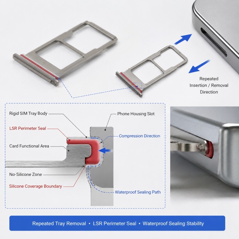
LSR overmolded SIM card tray seals can leak after repeated tray removal when the silicone sealing path is interrupted, the tray shifts during molding, corner compression becomes uneven or the tray slot pushes the seal in an unstable way during insertion and removal. A reliable waterproof SIM tray needs a continuous sealing profile, controlled no-silicone functional zones, stable tray positioning and repeatable compression against the final phone housing.
A waterproof SIM card tray is a small part, but it performs as a complete sealing system.
The rigid tray body provides the functional structure for the SIM card and the insertion path.
The surrounding LSR overmold provides the sealing function where the tray meets the phone housing.
The two functions should not be mixed.
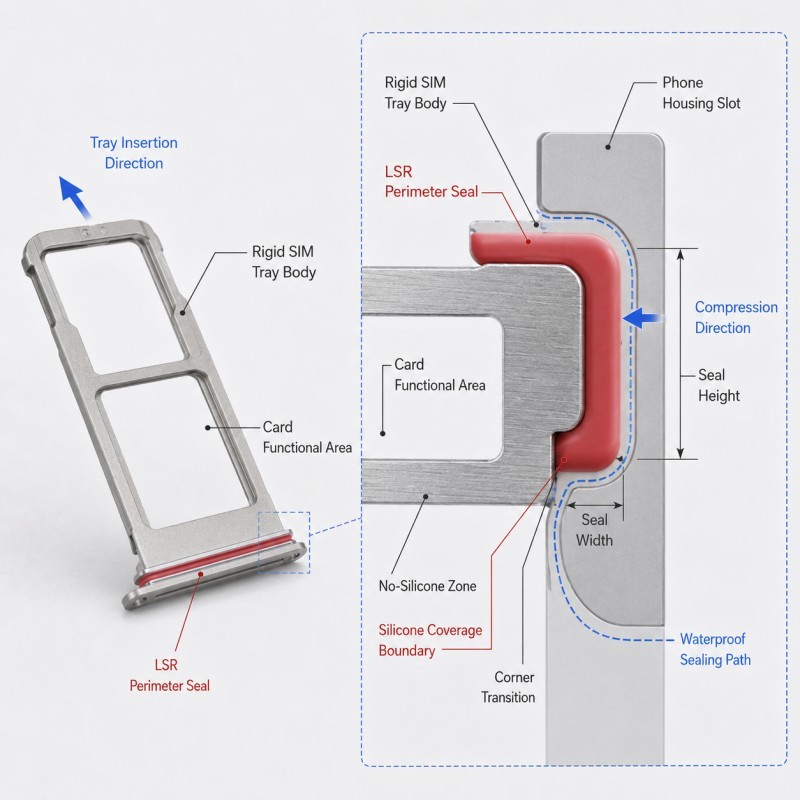
The card seating area, required tray-clearance surfaces and other functional features should remain clear, while the sealing region should stay continuous and well supported.
A tray may pass the first waterproof test and still become risky after repeated removal if the silicone boundary is exposed to scraping, twisting, uneven compression or local wear.
This is why repeated insertion and removal should be considered during DFM rather than only after tooling is complete.
For broader functional-area guidance, review how no-silicone zones should be designed in LSR overmolding.
What Changes During Repeated Tray Removal?
Repeated tray removal does not usually create one large failure event.
The more common problem is the accumulation of small changes around the same sealing path.
Possible repeated-use conditions include:
• Tray insertion
• Tray removal
• Slight tray twisting
• Uneven pulling force
• Friction against the slot
• Repeated compression and recovery
• Dust around the tray opening
• Cleaning
• Moisture exposure
• Cosmetic wear on the tray edge
A tray may appear normal after a few cycles.
After repeated use, however, the sealing structure may begin to show:
• Local edge wear
• Corner deformation
• Uneven compression
• Small boundary shift
• Partial seal flattening
• A scratched sealing surface
• Reduced recovery
• Water leakage under realistic use
The design target is therefore not only to make the tray waterproof when it is new.
The seal should remain functionally stable after the expected insertion and removal cycles.
Which Areas Must Remain No-Silicone Zones on a SIM Tray?
A waterproof SIM tray still contains functional regions that should not be covered by silicone.
Typical no-silicone zones can include:
• The card seating area
• Tray-clearance surfaces
• Required insertion guides
• Eject-pin related functional openings where applicable
• Positioning datums
• Mating or stopping surfaces that should remain dimensionally controlled
The purpose of the LSR overmold is to create a controlled sealing path, not to cover every visible tray surface.
If silicone enters a functional tray region, the result may include:
• Poor tray fit
• Increased insertion force
• Card-position interference
• Unstable seating
• Cosmetic mismatch
• Uncontrolled friction during removal
No-silicone zones should therefore be dimensioned from stable rigid features on the tray body rather than estimated visually from the outside silicone appearance.
The final drawing should show exactly where silicone is allowed and where it must stop.
Why Are Seal Continuity and Corner Geometry Critical?
A SIM tray seal works as a complete path.
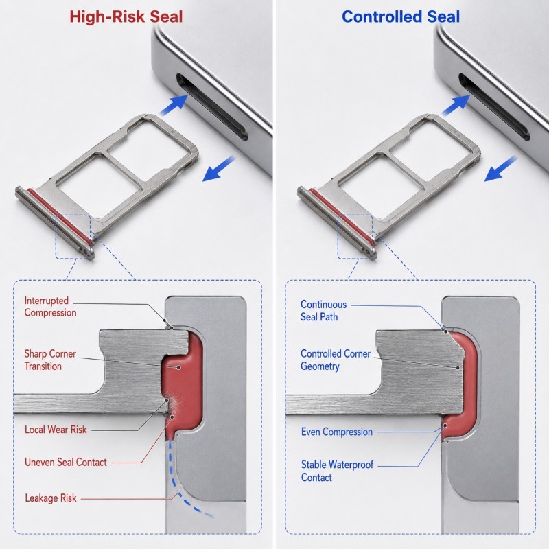
Its weakest point may be a short interrupted section, a corner transition or a local area where compression changes suddenly.
Important geometry includes:
• Perimeter continuity
• Corner radius
• Local silicone thickness
• Seal height
• Root support
• Distance to the tray edge
• Transition into flat sections
• Compression consistency around the full path
Corners are especially sensitive because the tray often changes direction while the surrounding slot geometry also changes.
If the corner profile is too sharp, too thin or poorly supported, repeated insertion and removal can accelerate local wear or deformation.
If one section of the seal sits higher or wider than another, the final compression may become uneven.
For related thickness guidance, review how wall thickness should be designed for LSR overmolding.
Why Should Compression Not Be Judged by Nominal Dimensions Alone?
The final compression of a SIM tray seal depends on more than the molded seal height.
It can also be affected by:
• Tray-body tolerance
• Slot tolerance
• Housing flatness
• Tray stop position
• Local warpage
• Silicone rebound
• Corner geometry
• Wear after repeated use
A seal that appears correct at nominal dimensions may still become over-compressed or under-compressed in realistic tolerance conditions.
Too much compression can create:
• High insertion force
• Seal scraping
• Permanent deformation
• Uneven recovery
• Local rolling or flattening
Too little compression can create:
• Weak contact pressure
• Water-leak paths
• Inconsistent sealing along the perimeter
Where a rigid feature controls the final closing distance, review how compression stops should be designed for LSR overmolded seals.
How Does Tray Position Affect Waterproof Sealing?
The rigid tray body must stay in a repeatable position during molding.
If the tray shifts, the seal geometry may change even when the mold cavity itself is correct.
Possible results include:
• Uneven seal thickness
• Different seal height on opposite sides
• A shifted corner profile
• Reduced sealing width in one area
• Functional interference in another area
• Left-right appearance variation
• Different insertion feel between samples
This becomes more critical on a small product because even a small offset can affect a significant portion of the sealing path.
The mold should therefore locate the tray from stable rigid datums and support it close to the seal region.
For detailed positioning guidance, review how insert positioning affects custom LSR overmolding quality.
Why Does Insertion and Removal Direction Matter?
A SIM tray seal is not loaded only when the tray is fully seated.
It is also loaded while the tray enters or leaves the slot.
If the housing slot or tray edge guides the seal poorly, the silicone may experience scraping, twisting or side loading before final compression is established.
High-risk conditions include:
• Abrupt slot edges
• A seal too close to a scraping path
• A tray corner that drags against the housing
• Uneven lead-in
• A user pulling the tray at a slight angle
• Dust increasing local friction
The DFM review should therefore consider the tray path, not only the final seated position.
The best design allows the tray to enter and exit with controlled seal contact rather than uncontrolled scraping.
SIM Card Tray Seal DFM Checklist
| DFM Item | What Engineers Should Confirm | Main Risk |
Functional zones | Card and tray functions remain clear | Silicone interferes with function |
Seal path | Perimeter sealing path is continuous | Water path interruption |
Corner geometry | Corners remain supportable and durable | Local wear or deformation |
Corner geometry | Seal is moldable and repeatable | Thin-edge damage |
Corner geometry | Final compression is realistic | Over- or under-compression |
Tray support | Rigid body supports the seal region | Unstable seal shape |
Compression stop | Final seated distance is controlled | Excessive deformation |
Tray position | Insert remains stable during molding | Uneven sealing |
| Slot path | Tray movement avoids uncontrolled scraping | Early seal wear |
| Surface quality | Critical surfaces are free from flash | Insertion interference |
| Validation | Repeated insertion, leak and wear tests are defined | First sample passes but real use fails |
The silicone mold design and tooling review should confirm tray datums, silicone coverage boundaries, corner geometry, compression condition, insert support, mold shut-off, gate, venting and demolding direction before mold steel is finalized.
How Should Repeated-Removal Waterproof Performance Be Validated?
A waterproof SIM tray should be validated in the real housing and under realistic removal conditions.
Recommended validation includes:
1. Visual Inspection
Check the silicone boundary for flash, scratches, corner defects, local lifting and uneven appearance.
2. Dimensional Inspection
Measure tray position, seal height, sealing width and critical housing-related dimensions.
3. First-Fit Assembly Review
Confirm that the tray inserts correctly and seats at the intended final position.
4. Repeated Insertion and Removal Cycling
Repeat the defined tray removal and insertion sequence and inspect the sealing path afterward.
5. Compression and Recovery Review
Confirm that the seal continues to recover after repeated use and does not show harmful flattening or instability.
6. Leak Testing
Perform the agreed waterproof test on the final assembly according to the actual product requirement.
7. Wear Inspection
Check whether tray edges, corners or housing contact regions cause local scraping or wear.
8. Pilot-Production Validation
Compare multiple cavities and consecutive production cycles before mass production approval.
The cycle count, waterproof target and pass/fail criteria should be defined by the actual customer product requirement rather than copied from a generic tray project.
How SiliconePlus Supports Waterproof Tray Overmolding DFM
SiliconePlus supports custom waterproof electronic-part overmolding projects from structural review through tooling, sampling, inspection and mass production.
Project support can include:
• Functional no-silicone-zone review
• Tray and housing sealing-path review
• Seal-corner and wall-thickness evaluation
• Compression-condition review
• Insert-positioning analysis
• Mold shut-off design
• Gate and venting review
• Precision mold development
• LSR injection molding
• Dimensional and appearance inspection
• Repeated-use and waterproof test support
• Pilot-production validation
Specific sealing geometry, tray tolerance, insertion-cycle requirement and waterproof acceptance criteria should always be confirmed according to the actual end product and customer validation method.
FAQ
Can a Waterproof SIM Tray Still Leak Even If the Seal Looks Normal?
Yes. A seal may look acceptable before assembly but still leak if compression is uneven, the corner wears locally or the tray path damages the silicone during repeated use.
Should Silicone Cover More Tray Area to Improve Waterproofing?
Not necessarily. Silicone should cover only the required sealing region. Extending it into functional tray zones can create insertion or fit problems.
Are Seal Corners More Sensitive Than Straight Sections?
Often yes. Corner geometry is more likely to experience changing compression, local wear and shape instability during repeated tray movement.
Does Higher Compression Always Improve Waterproof Performance?
No. Excessive compression can increase insertion force, cause wear or create permanent deformation. The correct compression depends on the full tray-and-slot system.
Can Repeated Tray Removal Affect Waterproof Performance Even If the Tray Still Fits?
Yes. The tray may still insert normally while the silicone sealing path gradually loses stability, especially at edges and corners.
Should Validation Use the Loose Tray Only?
No. The tray should be tested in the real or representative housing because waterproof performance depends on the final assembled condition.
Conclusion
A reliable LSR overmolded SIM card tray seal is not created by simply adding silicone around the tray edge.
The design should coordinate:
• No-silicone functional zones
• Continuous sealing path
• Corner geometry
• Wall thickness
• Compression condition
• Tray position
• Slot movement path
• Repeated insertion and removal
• Waterproof validation
The tray should remain functional while the silicone seal remains continuous, protected and repeatable throughout the product's expected service use.
These details should be reviewed during DFM before tooling, when the sealing path, tray structure and tolerance strategy can still be optimized efficiently.
Developing a Waterproof Electronic Tray or Small Housing Part?
If you are developing a waterproof SIM tray, side tray, port insert or another small electronic part with an LSR overmolded sealing structure, send your drawing, substrate material, silicone coverage area, waterproof target and estimated quantity to the SiliconePlus engineering team for a project-specific DFM review.