Why Do LSR Overmolded Perimeter Seals Lift Out of Plastic Grooves During Assembly?
- Share
- publisher
- SiliconePlus Engineering Team
- Issue Time
- Aug 27,2026
Summary
LSR overmolded perimeter seals can lift, roll or shift out of plastic grooves during assembly when groove support, silicone geometry, mating direction, compression or retention is not controlled. Reliable design requires a continuous groove-supported sealing path, stable plastic geometry, realistic assembly clearance and validation in the final mating housing.
Answer Excerpt
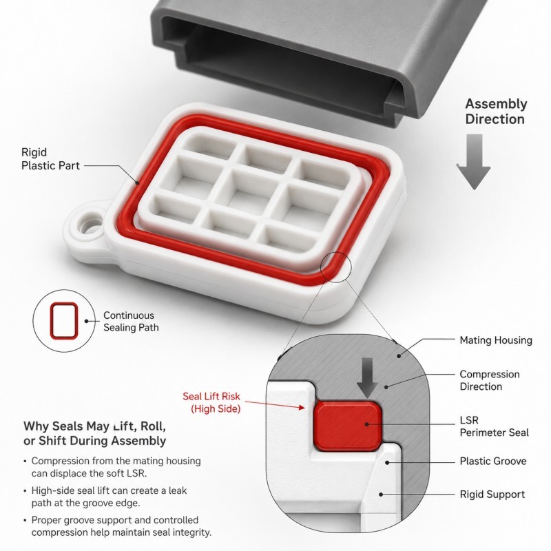
LSR overmolded perimeter seals can lift, roll or shift out of plastic grooves during assembly when the silicone profile is poorly supported, the mating component applies excessive side load, the seal is over-compressed or the groove provides insufficient resistance to the real load direction. A reliable design should keep the silicone seated and supported while allowing it to compress toward the mating surface rather than being dragged sideways.
A perimeter groove is not only a visual location for silicone.
It is part of the mechanical sealing system.
The rigid plastic controls the position of the LSR while the silicone provides the compliant sealing surface.
Before assembly, an overmolded seal may look perfectly continuous and dimensionally acceptable.
The real problem can appear when the mating housing begins to engage the silicone.
If the mating edge catches the seal and applies a strong lateral force, the soft material can stretch, roll or locally lift away from its intended position.
This may create an uneven sealing path even though the loose molded component passed visual inspection.
For this reason, groove geometry, silicone wall thickness, compression direction and the final mating path should be reviewed together during DFM.
What Does Seal Lifting Look Like During Assembly?
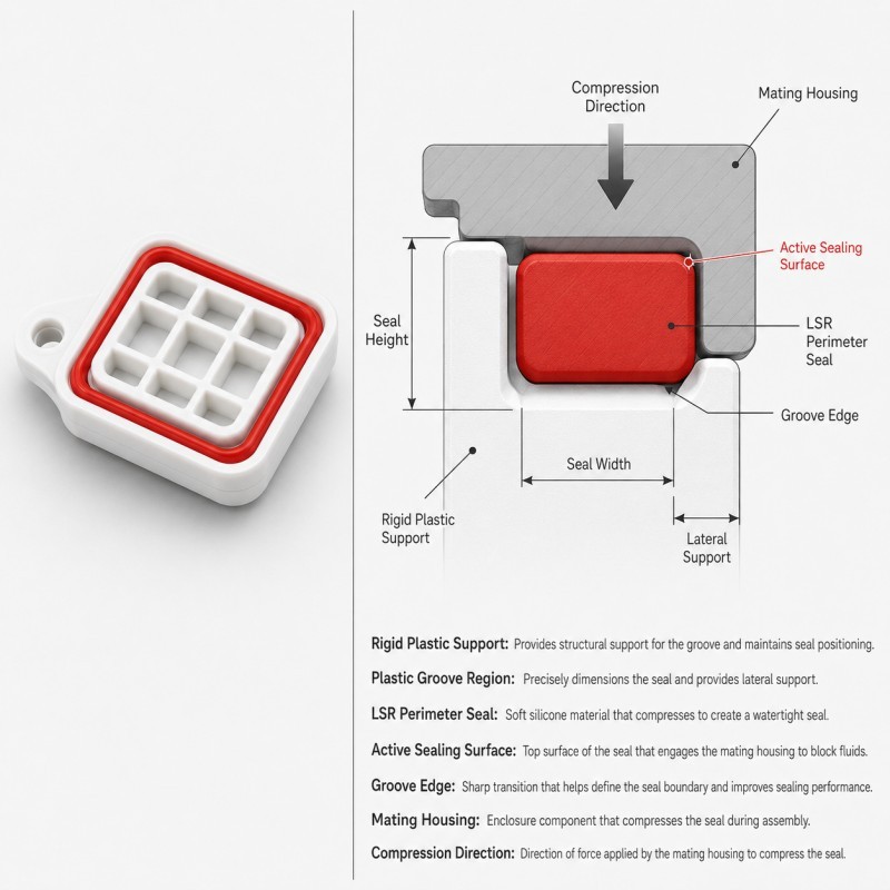
Seal lifting occurs when part of the overmolded silicone moves away from its intended supported position during assembly.
The seal does not always detach completely.
Typical symptoms may include:
• One corner lifting first
• A straight section being pulled sideways
• Silicone rolling over the groove edge
• Local bunching
• Uneven visible seal height
• One section becoming stretched
• Abnormal assembly force
• A local leakage path after assembly
The silicone may partially recover after the mating component is removed.
This can make the problem difficult to diagnose.
A technician may remove the part, inspect the seal and see only a small deformation.
The actual failure occurred while the housing was being assembled.
For this reason, loose-part inspection cannot completely replace assembly observation.
What Does the Plastic Groove Actually Do?
The plastic groove can perform several functions depending on the product structure.
It may help control:
• Silicone position
• Seal width
• Seal height
• Flow boundary
• Lateral support
• Compression direction
• Sealing-path continuity
The groove should prevent unnecessary sideways movement while still allowing the active silicone surface to deform toward the mating component.
A groove that provides too little lateral support can allow the whole soft section to move.
A groove that constrains the silicone too aggressively can also create problems if the seal has no space to deform during compression.
The objective is therefore not simply to make the groove deeper.
The groove, silicone profile and mating gap must work together.
Because hidden groove geometry is highly product-specific, there is no universal depth or width that should be copied into every overmolded sealing design.
Why Are Tall or Poorly Supported Seals More Likely to Lift?
A sealing profile needs flexibility to conform to the mating surface, but it also needs enough support to remain in position.
A tall silicone feature creates a longer lever arm above the rigid plastic support.
If the mating housing contacts the upper part of the seal from the side, the applied force can create bending or peeling instead of direct compression.
Possible results include:
• Sideways seal movement
• Groove-edge loading
• Local rolling
• Silicone stretching
• Corner lifting
• Increased assembly force
A lower profile is not automatically better.
If the seal becomes too low, it may not create the required interference with the mating component.
The DFM target is therefore to balance active sealing height with sufficient lateral support.
The complete cross-section should be reviewed from the rigid plastic base to the final sealing contact surface.
How Can the Mating Housing Pull the Seal Sideways?
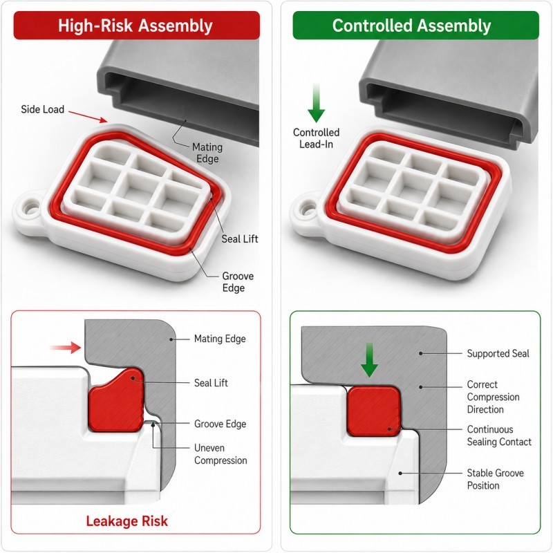
The mating component should compress the seal toward its intended final position.
Problems occur when the mating edge behaves more like a scraper than a compression surface.
High-risk conditions may include:
• Abrupt lead-in edges
• Angled assembly
• Excessive initial interference
• Rough mating surfaces
• Local burrs
• Housing misalignment
• Insufficient assembly clearance
When the housing first touches the silicone, friction creates a tangential force.
If this tangential force becomes too large relative to the support provided by the groove, the silicone may be dragged sideways.
The same design may assemble correctly in a perfectly aligned laboratory fixture but become unstable during normal manual production assembly.
For this reason, the real assembly path and normal positional variation should be included in DFM.
How Does Excessive Compression Increase Seal-Lift Risk?
More compression does not automatically create a better seal.
If the final mating gap becomes too small, the silicone must deform more than intended.
Depending on the cross-section, excessive compression can cause:
• Sideways bulging
• Seal rolling
• Local extrusion
• Groove-edge loading
• Increased assembly force
• Permanent deformation
• Local lifting
The actual compression condition depends on several dimensions:
• Seal height
• Groove geometry
• Mating-housing position
• Plastic-part tolerance
• Housing flatness
• Assembly-stop position
• Mold-cavity variation
Minimum, nominal and maximum assembly conditions should therefore be reviewed.
Where a rigid feature controls the final closing position, review how compression stops should be designed for LSR overmolded seals.
When Does a Groove Seal Need Additional Mechanical Retention?
Some overmolded seals rely mainly on material bonding and groove support.
Other applications may benefit from additional mechanical retention when the silicone experiences significant peel, side loading or repeated assembly stress.
Possible retention concepts can include:
• Local undercuts
• Through-features
• Retention windows
• Edge wraparound
• Interlocking groove geometry
However, these features should not be added blindly.
They can also affect:
• Silicone flow
• Air evacuation
• Plastic strength
• Mold shut-off
• Demolding
• Local wall thickness
The retention structure should resist the actual load direction.
A feature designed only for vertical pull may not effectively control a seal that is being dragged sideways by a mating housing.
The hidden retention structure must therefore be designed from the real assembly load, not copied from another product.
For broader guidance, review when LSR overmolding needs mechanical retention.
Why Are Groove Corners More Sensitive to Seal Lifting?
Corners combine direction change, local stiffness and sealing continuity in a small region.
At a straight section, the silicone is usually supported along a relatively consistent path.
At a corner, several variables may change at the same time:
• Seal direction
• Groove curvature
• Local silicone thickness
• Plastic support
• Mating-housing contact
• Flow behavior during molding
• Assembly friction
This is why lifting may begin at one corner even when the long straight sections remain seated.
A corner should remain part of the same continuous sealing path.
The transition should avoid an unnecessary sharp unsupported shape or sudden change in seal cross-section.
Validation should also inspect corners individually rather than assuming that a successful straight section represents the entire perimeter.
How Does Plastic Insert Position Affect the Groove Seal?
The rigid plastic insert must remain stable during LSR injection.
If the insert shifts or deforms, the relationship between the groove and the silicone cavity also changes.
Possible results include:
• Uneven seal thickness
• Different seal height around the perimeter
• Boundary shift
• Local flash
• Reduced groove support
• Different compression from one side to another
This is especially important on thin plastic housings where injection pressure or thermal conditions may affect insert position.
The mold should locate the rigid component from repeatable datums and support it close to critical sealing regions where the product structure permits it.
For related process guidance, review how insert positioning affects custom LSR overmolding quality.
Plastic Groove Perimeter Seal DFM Checklist
| DFM Item | What Engineers Should Confirm | Main Risk |
Sealing path | Perimeter seal remains continuous | Local leakage |
Groove support | Plastic supports the seal laterally | Seal shifts or lifts |
Seal height | Profile matches real mating gap | Under- or over-compression |
Seal width | Cross-section remains stable | Rolling or distortion |
Corner geometry | Direction changes remain supported | Corner lifting |
Mating lead-in | Housing compresses instead of scraping | Side loading |
Assembly direction | Real production path is defined | Seal dragged sideways |
Mechanical retention | Retention matches actual load | Peel or lift failure |
| Plastic stiffness | Groove remains dimensionally stable | Seal position changes |
| Insert positioning | Plastic part remains repeatable in mold | Uneven seal geometry |
| Validation | Assembly, compression and leak tests are defined | Loose part passes but assembly fails |
The silicone mold design and tooling review should confirm the plastic insert datum, groove geometry, silicone cross-section, mechanical retention, mating direction, mold shut-off, parting line, gate, venting and demolding before mold steel is finalized.
How Should Groove-Seal Retention Be Validated?
Groove-seal retention should be validated in the real or representative mating assembly.
Recommended validation includes:
1. Loose-Part Inspection
Check seal height, perimeter continuity, corners, flash and visible groove position.
2. Assembly Observation
Watch how the mating housing first contacts the silicone and identify whether the seal is compressed or dragged sideways.
3. Final Assembly Inspection
Check for lifting, rolling, local extrusion or uneven seal exposure.
4. Compression Review
Confirm the minimum, nominal and maximum assembly conditions where required.
5. Corner Inspection
Inspect individual corners after assembly because they may respond differently from straight sections.
6. Retention Evaluation
Where appropriate, apply representative side or peel loading rather than relying only on vertical pull force.
7. Leak Testing
Complete the agreed air-leak, pressure-decay, immersion or other waterproof test on the final assembly.
8. Repeated Assembly Testing
Where the product is designed for repeated opening or servicing, repeat the defined assembly cycle and inspect the seal afterward.
9. Pilot-Production Validation
Compare multiple mold cavities and realistic plastic-insert lots before mass-production approval.
The load, compression, cycling and waterproof acceptance limits should always come from the actual end-product requirement.
How SiliconePlus Supports Silicone-Over-Plastic Seal DFM
SiliconePlus supports custom silicone-over-plastic and precision LSR sealing projects from structural review through tooling, sampling, inspection and mass production.
Project support can include:
• Plastic insert and groove DFM
• Silicone perimeter-seal review
• Wall-thickness analysis
• Compression-condition review
• Mechanical-retention design
• Insert-positioning and support review
• Mold shut-off and parting-line analysis
• Gate and venting review
• Precision mold development
• LSR injection molding
• Dimensional and appearance inspection
• Assembly and waterproof test support
• Pilot-production validation
Specific groove geometry, silicone hardness, compression, retention structure and waterproof acceptance criteria should always be confirmed according to the actual product and mating assembly.
FAQ
Does a Deeper Plastic Groove Always Prevent Seal Lifting?
No. Groove depth is only one variable. Seal height, width, support, retention, mating direction and compression must be evaluated together.
Why Does the Seal Lift Only During Assembly?
The mating component may apply side load or friction that is not present during loose-part inspection.
Does Softer Silicone Stay in the Groove Better?
Not necessarily. Softer LSR can conform easily, but a tall or poorly supported soft seal may also move more easily under lateral load.
Does Every Groove Need an Undercut?
No. Mechanical-retention requirements depend on the real material system, groove geometry and expected loading. An undercut should have a functional reason.
Why Do Corners Lift Before Straight Sections?
Corners combine a change in direction, local geometry and assembly friction, making them more sensitive to unsupported deformation.
Should Seal Retention Be Tested with a Vertical Pull Test Only?
No. If the actual assembly applies side load, peeling or repeated friction, validation should reproduce those directions where appropriate.
Conclusion
An LSR perimeter seal does not remain stable simply because it was molded inside a plastic groove.
Reliable retention requires coordinated control of:
• Groove support
• Silicone cross-section
• Seal height
• Corner geometry
• Mating lead-in
• Compression
• Mechanical retention
• Plastic insert position
• Assembly direction
• Final validation
The mating component should compress the silicone toward the intended sealing surface rather than drag the seal sideways out of its supported position.
These conditions should be reviewed during DFM before tooling, when the groove, silicone geometry and assembly interface can still be optimized efficiently.
Developing an LSR Overmolded Perimeter Seal?
If you are developing a plastic housing, cover, connector or another component with an integrated LSR perimeter seal, send your 3D drawing, substrate material, sealing groove, mating-part drawing and waterproof requirements to the SiliconePlus engineering team for a project-specific DFM review.