Why Should the Mating Housing Be Reviewed Before LSR Overmolding Automotive Connector Terminals?
- Share
- publisher
- SiliconePlus Engineering Team
- Issue Time
- Nov 20,2026
Summary
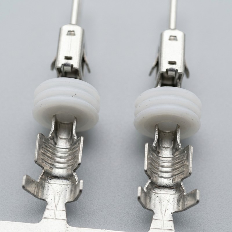
Before developing an LSR overmolding tool for automotive connector terminals, OEMs should review the mating housing, assembly direction, available clearance, terminal positioning and silicone envelope. Evaluating the complete interface helps identify potential interference before tooling and sampling.
Answer Excerpt
Before LSR overmolding automotive connector terminals, engineers should review the mating housing together with the metal insert and silicone structure. Housing dimensions, assembly direction, terminal position, clearance and the final overmolded envelope can affect whether the component fits correctly after molding. Reviewing the mating interface before tooling helps identify potential interference early.
Why Is the Mating Housing Important in Connector Overmolding?
An automotive connector terminal should not be evaluated only as an isolated metal component.
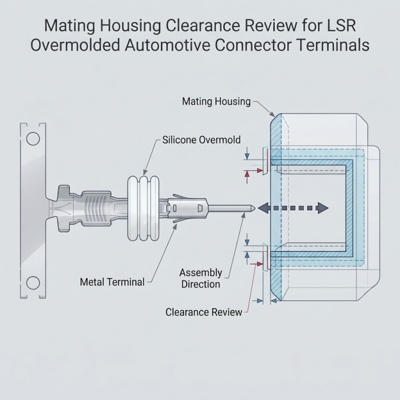
After silicone overmolding, the finished part may need to fit into a connector housing or another mating structure. The available space around the terminal can influence the permitted silicone coverage, local thickness and overall component envelope.
If the mating housing is not considered during early engineering review, a molded part may look acceptable on its own but create interference during assembly.
For this reason, the terminal, silicone overmold and mating structure should be reviewed as one connected interface.
1. Confirm the Actual Assembly Direction
The engineering team should understand how the overmolded terminal enters or connects with the mating component.
Review the intended:
Insertion direction
Terminal orientation
Assembly sequence
Locating and support features
Areas that must remain accessible
Possible movement during installation
The assembly direction helps identify which silicone surfaces may contact the housing during insertion and which areas need additional clearance.
2. Check the Available Space Around the Silicone
The final silicone envelope must be compatible with the available space in the mating housing.
Important areas to review include:
Clearance around the molded silicone sections
Space near metal-to-silicone transitions
Local openings and recesses
Housing walls and locating features
Areas where the silicone could be compressed during assembly
Do not assume that the silicone can simply be made thicker to improve protection or sealing. Additional material may change the assembly envelope and create interference.
The required clearance should come from the actual component drawings and assembly requirements rather than a universal estimated value.
3. Separate Functional Metal Areas from Silicone Areas
Metal terminals may contain surfaces that must remain exposed for electrical contact, welding, connection or positioning.
The engineering drawing should distinguish these functional metal areas from the intended silicone coverage.
This review should consider both the terminal itself and the mating housing. A metal area may need to remain accessible not only for electrical reasons but also because it participates in locating or assembling the terminal.
For more detail, see our guide to metal terminal overmolding design.
4. Review Tolerance Stack-Up Before Tooling
The final assembly depends on more than one dimension.
Relevant contributors may include:
Metal terminal dimensions
Terminal positioning variation
Silicone molded dimensions
Mating housing dimensions
Locating feature tolerances
Assembly clearances
These dimensions should be reviewed together to identify the critical fit conditions.
A terminal that meets its individual drawing may still create an assembly problem when combined with a housing at the opposite end of its tolerance range.
The engineering team should identify the functional dimensions that control insertion, positioning and final fit before the mold design is finalized.
5. Evaluate the Assembly Using Real Components
Where available, provide the mating housing, assembly drawing or a representative physical sample during engineering review.
A 3D model helps evaluate geometry, but physical components can also reveal practical handling and assembly conditions that may not be obvious from an isolated terminal drawing.
The review should establish:
Whether the overmolded component can be installed as intended
Whether silicone contacts unintended housing surfaces
Whether the terminal remains correctly positioned
Whether the assembly sequence is practical
Which dimensions require confirmation during sampling
What Should Be Reviewed Before Tooling?
| Review Item | Information to Confirm | Purpose |
Mating housing | 2D drawing or 3D model | Understand available space |
Assembly direction | Insertion and installation sequence | Identify possible interference |
Terminal position | Functional locating references | Maintain correct alignment |
Silicone envelope | Intended coverage and outer dimensions | Check housing clearance |
| Exposed metal | Contact and functional areas | Avoid unwanted coverage |
| Tolerances | Critical dimensions of both components | Review stack-up |
| Assembly validation | Fit and acceptance requirements | Confirm the actual interface |
How SiliconePlus Supports Automotive Connector Overmolding
SiliconePlus supports custom LSR overmolding projects involving metal inserts and automotive connector-related silicone components.
Engineering review can consider the supplied drawings, samples, silicone coverage requirements, metal insert structure, mold design and intended assembly conditions before tooling.
Our focus is custom silicone overmolded components rather than complete automotive connector assemblies.
For more information, see our custom automotive connector silicone components and LSR injection molding capabilities.
Conclusion
The mating housing should be reviewed before developing an LSR overmolding tool for an automotive connector terminal.
The key is to evaluate the metal insert, silicone envelope, available clearance, assembly direction and tolerance stack-up together.
Providing the mating housing drawing or physical sample early can help identify potential interference before tooling and sample approval.
Developing an LSR-overmolded automotive connector component?
Send your terminal drawing, 3D model, mating housing information or physical samples to SiliconePlus. Our team can review the component structure and discuss the manufacturing requirements for your custom project.