Why Do Precision LSR Overmolded Parts Change Size After Molding?
- Share
- publisher
- siliconeplus
- Issue Time
- Jul 20,2026
Summary
Precision LSR overmolded parts may change size after demolding, cooling, post-curing or storage. This guide explains how material grade, hardness, mold temperature, cavity pressure, gate direction, wall thickness, inserts, measurement timing and production conditions affect silicone shrinkage and dimensional stability.
Introduction
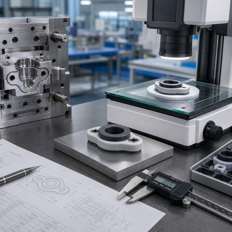
A precision LSR overmolded part may match the drawing immediately after molding but show a different dimension after cooling, storage, post-curing, assembly, or environmental testing.
The difference may be small, but for a sealing lip, connector interface, contact-pad boundary, sensor housing, medical component, or wearable electronic module, a small dimensional change can affect:
- Assembly fit
- Waterproof compression
- Contact-pad exposure
- Hole position
- Insert alignment
- Button movement
- Bonding-edge width
- Cosmetic appearance
- Electrical function
- Final product tolerance
These problems are often described simply as “silicone shrinkage.”
However, the final dimension of an LSR overmolded part is not controlled by the silicone material alone.
It is also affected by:
- Mold-cavity dimensions
- Silicone material grade
- Shore A hardness
- Mold temperature
- Demolding temperature
- Curing time
- Cavity pressure
- Gate position
- Material-flow direction
- Wall thickness
- Insert dimensions
- Insert deformation
- Post-curing
- Measurement timing
- Production consistency
For precision overmolding projects, the correct question is not only:
“What is the shrinkage rate of LSR?”
The more useful question is:
“How should the mold, material, process, insert, measurement method, and tolerance standard be coordinated to produce the required final dimension repeatedly?”
Answer Excerpt
LSR overmolded parts can change size after molding because liquid silicone rubber expands inside the heated mold and then contracts after demolding and cooling.
The final shrinkage is not one fixed percentage for every product. It depends on material grade, hardness, filler system, mold temperature, demolding temperature, cavity pressure, gate direction, part thickness, post-curing, and product geometry.
For overmolded parts, the plastic, metal, FPC, cable, or electronic insert can restrain silicone movement and create different shrinkage conditions around the same component.
Reliable dimensional control requires material-specific trial data, mold compensation, stable process parameters, controlled inserts, defined measurement timing, and pilot-production validation before mass production.
Supplier processing guides give different typical ranges for different LSR systems and specifically warn that material grade and processing conditions strongly affect final shrinkage. These figures should be used as preliminary references rather than guaranteed values for a finished custom part.
1. What Does LSR Shrinkage Mean?
LSR shrinkage is the dimensional reduction that occurs as molded liquid silicone rubber cools and reaches its final cured condition.
Unlike many thermoplastic materials, LSR behaves differently inside a heated mold.
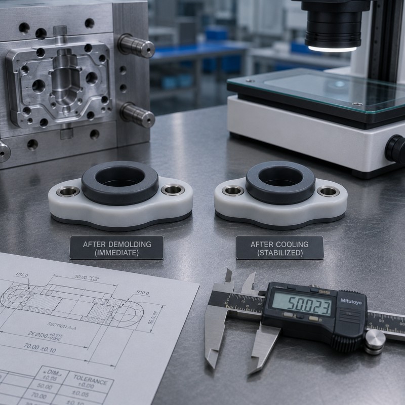
During molding, the liquid silicone enters the hot cavity, expands under heat and pressure, and cures. After the part is removed from the mold and cools, its dimensions may decrease.
Shrinkage may affect:
- Overall length
- Overall width
- Product height
- Hole diameter
- Sealing-lip height
- Silicone-layer thickness
- Opening position
- Edge coverage
- Groove dimensions
- Distance between functional features
Shrinkage is normally considered during mold design by making the cavity larger or otherwise compensating for the expected dimensional change.
However, compensation should not be based only on one general percentage.
The actual product must be evaluated according to its material, geometry, inserts, process, and required tolerances.
2. Why Does the Part Change Size After Demolding?
The LSR part is still hot when it is removed from the mold.
As it cools, several changes may occur:
- Thermal contraction
- Material relaxation
- Release of cavity pressure
- Recovery from demolding deformation
- Redistribution of internal stress
- Continued dimensional stabilization
The dimension measured immediately after demolding may therefore differ from the dimension measured after the part reaches room temperature.
Thin areas may cool faster than thick areas.
A large product may require more time to stabilize than a small sealing component.
A part stretched during demolding may also temporarily appear larger or distorted before recovering.
For precision parts, the drawing and inspection plan should define when the measurement will be taken.
3. LSR Shrinkage Is Not One Universal Percentage
It is risky to say that all LSR products shrink by one fixed percentage.
Published processing guidance shows that shrinkage varies among silicone systems and depends heavily on the specific material and process. Dow’s guide for one XIAMETER LSR system reports shrinkage after demolding and cooling and identifies mold temperature, demolding temperature, cavity pressure, gate location, part dimensions, and post-curing as influencing factors. Wacker provides a broader typical range for its material families and states that precision parts require preliminary trials and fine adjustment.
The actual value may change when the project changes:
- Silicone supplier
- Material series
- Hardness
- Color formulation
- Self-bonding system
- Medical-grade material
- High-temperature material
- Conductive formulation
- Product thickness
- Mold temperature
- Post-curing requirement
A shrinkage figure from an unrelated material data sheet should not automatically be applied to a new custom mold.
4. Material Grade Affects Dimensional Change
Different LSR grades are formulated for different requirements.
Examples include:
- General-purpose LSR
- Self-adhesive LSR
- Medical-grade LSR
- Food-contact LSR
- High-tear-strength LSR
- High-temperature LSR
- Low-compression-set LSR
- Electrically conductive silicone
- Optical silicone
- Low-temperature-curing LSR
These formulations may have different:
- Filler content
- Density
- Hardness
- Flow behavior
- Curing behavior
- Bonding mechanism
- Thermal response
- Shrinkage behavior
Changing the material after mold completion may therefore change the final product dimensions.
If a project moves from a standard LSR to a self-bonding or special-performance material, the engineering team should review whether the existing mold compensation remains suitable.
New molded samples should be measured before production approval.
5. Hardness Can Influence Shrinkage—but It Is Not the Only Factor
Silicone hardness may affect shrinkage because different hardness grades often use different material formulations and filler systems.
Higher-hardness materials may show different dimensional behavior from softer grades.
However, the relationship should not be simplified into:
“Harder silicone always shrinks less.”
The final result also depends on:
- Material family
- Filler content
- Mold temperature
- Cavity pressure
- Product thickness
- Gate direction
- Post-curing
- Insert restriction
- Measurement method
A 30 Shore A sealing membrane and a 70 Shore A overmolded handle cannot be compared only by hardness.
The complete material data and product structure should be evaluated.
6. Mold Temperature Changes the Final Dimension
LSR requires a heated mold for curing.
Mold temperature affects:
- Curing speed
- Material expansion
- Cycle time
- Demolding condition
- Surface quality
- Bonding
- Final shrinkage
If the mold temperature is unstable, the product may show dimensional variation between:
- The beginning and end of production
- Different mold cavities
- Different production shifts
- Different machines
- Different sample rounds
An excessively low temperature may result in incomplete or unstable curing.
An excessively high temperature may increase process stress, affect sensitive inserts, or change the final dimensional result.
The correct mold temperature should be established for the exact material, product geometry, insert, bonding requirement, and cycle time.
7. Demolding Temperature and Demolding Method Matter
The temperature of the product at demolding affects how it behaves after leaving the cavity.
A hotter product may:
- Be softer
- Stretch more during removal
- Deform around undercuts
- Recover differently during cooling
- Show greater temporary dimensional change
A part that is pulled aggressively from the mold may become:
- Elongated
- Twisted
- Oval
- Bent
- Locally thinned
- Distorted around holes or lips
These changes may be temporary or permanent.
Demolding design should therefore consider:
- Draft
- Undercuts
- Product flexibility
- Part-removal direction
- Robot or manual removal
- Support during cooling
- Part placement after removal
- Inspection timing
A dimension problem caused by demolding should not be corrected only by changing the mold cavity.
8. Cavity Pressure Affects Material Compression
The pressure inside the cavity can influence the final molded condition.
Cavity pressure may be affected by:
- Injection volume
- Injection speed
- Holding pressure
- Gate size
- Runner balance
- Venting
- Mold clamping
- Insert fit
- Cavity filling sequence
Higher cavity pressure may compress the material differently before curing.
When the part is removed and pressure is released, the material may relax and change dimension.
Unstable pressure can create variation in:
- Product thickness
- Sealing-lip height
- Flash
- Overall dimensions
- Insert movement
- Cavity-to-cavity consistency
The process should use a stable filling window rather than excessive pressure to compensate for poor venting or flow balance.
9. Gate Position Can Create Directional Shrinkage
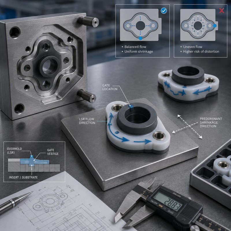
Silicone does not always shrink equally in every direction.
Material flow can produce different dimensional behavior:
- Along the flow direction
- Across the flow direction
- Near the gate
- At the end of filling
- Around inserts
- Around thin sections
Dow’s LSR processing guide notes that shrinkage in the direction of material flow can differ from shrinkage perpendicular to the flow direction.
For a long narrow component, this difference may affect:
- Overall length
- Hole spacing
- Sealing-line position
- Connector alignment
- FPC coverage
- Cosmetic symmetry
Gate position should therefore be reviewed together with the critical dimension direction.
A gate selected only for easy mold machining may create an unfavorable flow and shrinkage pattern.
10. Wall Thickness Changes Cooling and Shrinkage Behavior
Thick and thin silicone sections do not behave identically.
Thin sections may:
- Cool faster
- Shrink differently
- Stretch during demolding
- Become sensitive to flash
- Show greater dimensional instability
Thick sections may:
- Retain heat longer
- Cure differently
- Cool more slowly
- Create internal stress
- Affect nearby thin features
Supplier guidance also indicates that part dimensions and thickness can influence shrinkage behavior.
Common high-risk structures include:
- Thin sealing lips connected to thick bases
- Thick strain reliefs connected to thin membranes
- Large corner buildup
- Thick silicone around a metal insert
- Thin silicone over a wide plastic housing
- Sudden thickness transitions
Where possible, gradual thickness transitions can improve molding and dimensional stability.
11. Product Geometry Can Cause Nonuniform Shrinkage
A simple flat test specimen does not behave like a complex overmolded part.
Product geometry may include:
- Ribs
- Grooves
- Holes
- Sealing lips
- Undercuts
- Curved surfaces
- Thick corners
- Thin membranes
- Mechanical locking features
- Wraparound edges
These features can restrict or redirect silicone movement during cooling.
For example:
- A circular silicone ring may shrink inward.
- A long sealing lip may shrink differently along its length.
- A wraparound structure may be restrained by the insert.
- A mechanical-locking hole may prevent free movement.
- A thin edge may distort before the main body stabilizes.
Shrinkage should therefore be reviewed on the complete 3D structure.
12. Post-Curing Can Create Additional Dimensional Change
Some silicone projects require post-curing to achieve the intended material, odor, volatile, mechanical, or application-related requirements.
Post-curing exposes the part to additional heat after molding.
This may cause:
- Additional shrinkage
- Further material stabilization
- Hardness change
- Color change
- Dimensional relaxation
- Insert stress
- Bonding-interface stress
Dow’s guide notes additional dimensional reduction from post-curing for the specific material system covered by that document. The actual result depends on the selected grade and post-curing conditions.
If the final production part will be post-cured, the sample should also be inspected after the same process.
A pre-post-cure sample should not be used as the final dimensional reference.
13. Inserts Restrain Silicone Shrinkage
In an overmolded part, silicone is not free to shrink like a separate molded component.
It may be bonded or mechanically locked onto:
- Plastic
- Metal
- FPC
- Cable
- Electronic components
- Glass
- Ceramic
- Pre-molded silicone
The insert can restrict silicone movement in some areas while allowing movement in others.
This may create:
- Uneven silicone thickness
- Warped edges
- Local stress
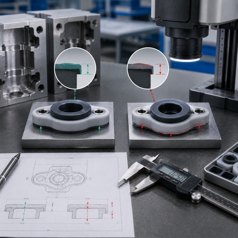
- Shifted sealing lips
- Distorted holes
- Asymmetric dimensions
- Bonding-edge tension
- Different shrinkage on each side
The overmolded structure must therefore be evaluated as a multi-material component.
A shrinkage value measured on a pure silicone test plaque may not directly predict the final dimension of silicone bonded to a rigid insert.
14. Plastic Inserts Add Their Own Dimensional Variation
Silicone over plastic projects require both the plastic insert and the overmolded silicone structure to remain dimensionally stable.
Plastic inserts may already contain variation before LSR molding.
Possible factors include:
- Plastic molding shrinkage
- Warpage
- Moisture absorption
- Residual stress
- Storage deformation
- Wall-thickness variation
- Different plastic batches
- Different molding machines
- Supplier variation
The plastic may then experience additional heat and pressure during LSR overmolding.
Engineers should also evaluate how to prevent plastic insert deformation before finalizing the silicone mold compensation.
A change in the plastic insert can alter:
- Final overall dimensions
- Silicone-layer thickness
- Sealing-lip position
- Hole position
- Mold shutoff
- Bonding width
- Assembly fit
SiliconePlus already identifies insert tolerance, substrate deformation, curing, demolding, and process stability as major contributors to dimensional variation in precision overmolding.
Before mold development, actual plastic inserts from representative production batches should be measured.
15. Metal and FPC Inserts Create Different Constraints
Metal inserts are generally rigid, but their dimensions can still vary because of:
- Stamping tolerance
- CNC machining
- Plating thickness
- Burrs
- Flatness
- Bending
- Thermal expansion
FPC silicone overmolding introduces different dimensional and positioning risks:
- Thickness variation
- Bowing
- Stretching
- Stiffener position
- Pad-location variation
- Loading tension
- Flexible movement
The mold and fixture must hold each insert accurately while allowing the intended silicone structure to form.
For FPC components, a small dimensional shift may affect:
- Contact-pad exposure
- Test-point position
- Silicone coverage boundary
- Bending zone
- Connector alignment
The inspection plan should therefore include both the silicone dimensions and insert position.
16. Mold Compensation Must Be Confirmed Before Final Tooling
Mold compensation means adjusting the mold cavity so the cooled, finished product reaches the required final dimension.
A simple example is making the mold cavity slightly larger to account for expected silicone shrinkage.
However, precision compensation may need different corrections for:
- Length
- Width
- Height
- Hole diameter
- Sealing-lip height
- Local thickness
- Flow direction
- Insert boundary
The compensation should be based on:
- Selected material
- Supplier data
- Similar production experience
- Product geometry
- Mold-flow direction
- Insert structure
- Post-curing
- Preliminary trials
A DFM review should identify shrinkage-sensitive dimensions before steel cutting because major dimensional correction after mold completion may require insert replacement or mold modification.
17. Why the First Mold Trial May Need Dimensional Adjustment
Material data can provide a starting point, but it cannot predict every feature of a complex custom component.
The first mold trial may reveal:
- Overall part too small
- Overall part too large
- Hole too tight
- Sealing lip too short
- Uneven silicone coverage
- Insert position affecting measurement
- Different shrinkage by direction
- Different cavity results
- Post-cure dimensional change
- Demolding deformation
The engineering team should determine whether the cause is:
- Mold compensation
- Material
- Process
- Insert
- Demolding
- Measurement
- Post-curing
- Assembly
Not every dimensional problem should immediately lead to mold machining.
The process and measurement conditions should be stabilized before changing the tool.
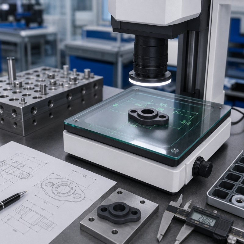
18. Measurement Timing Must Be Standardized
A precision dimension should not be measured at random times.
The inspection plan should define:
- Cooling time
- Conditioning time
- Measurement temperature
- Measurement humidity, when relevant
- Pre- or post-curing condition
- Free state or assembled state
- Measurement fixture
- Measurement force
- Product orientation
- Measurement equipment
Soft silicone can deform under the force of a caliper or fixture.
A thin sealing lip may produce different readings when pressed from different directions.
Suitable measurement methods may include:
- Optical measurement
- Vision inspection
- Profile projector
- Height gauge
- Non-contact measurement
- Custom inspection fixture
- Pin or plug gauge
- Functional assembly gauge
The measurement method should match the function and geometry of the feature.
19. Why Samples Pass but Production Dimensions Drift
A small sample run may be produced under closely controlled conditions.
During sampling:
- One material batch is used
- Inserts are selected carefully
- Mold temperature is monitored closely
- Production time is short
- Engineers inspect every part
- Parts are allowed to cool properly
Mass production introduces:
- Longer continuous runs
- Multiple material batches
- Multiple insert batches
- Operator changes
- Mold-temperature variation
- Equipment variation
- Different demolding timing
- Cavity wear
- Packaging pressure
- Different measurement operators
SiliconePlus’s existing prototype-to-production guidance also emphasizes that sample quality does not automatically prove repeatable mass-production quality.
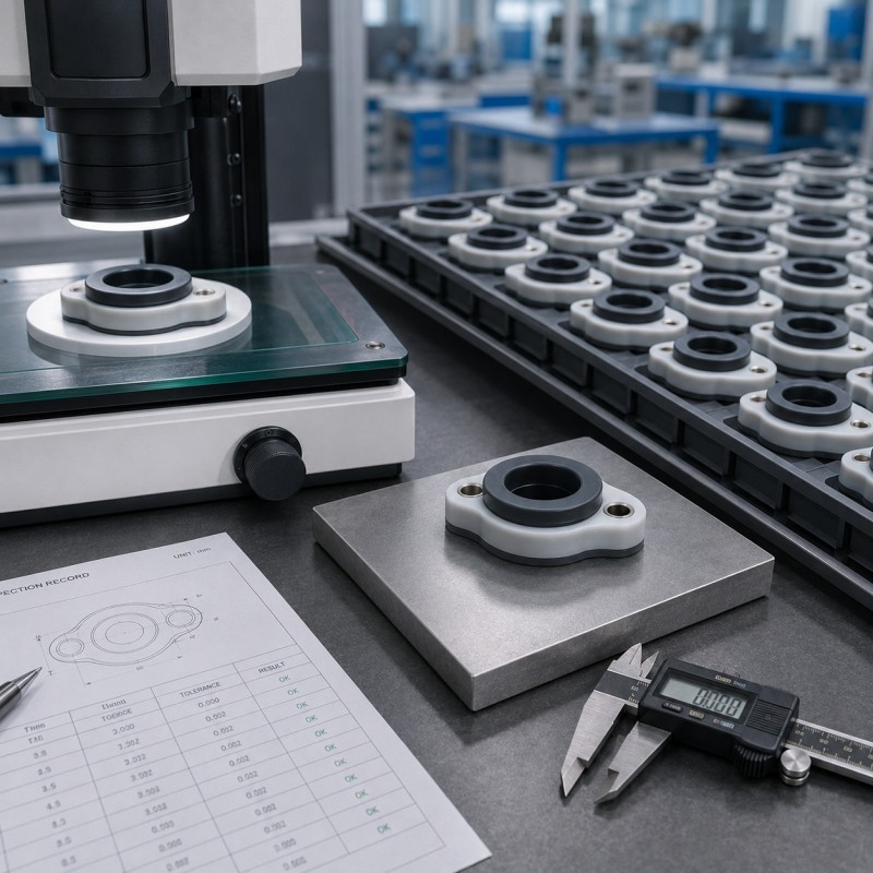
Pilot production should therefore evaluate dimensional stability across:
- Every cavity
- Beginning and end of the run
- Different insert batches
- Different production shifts
- Post-curing
- Packaging and storage
- This dimensional verification is part of keeping LSR overmolded parts consistent from prototype to mass production.
20. A Practical Dimensional-Failure Investigation
When a precision LSR overmolded part is too large, too small, or inconsistent, investigate the issue systematically.
Recommended sequence:
- Confirm the drawing revision.
- Confirm the exact failed dimension.
- Confirm the measurement method.
- Confirm when the part was measured.
- Compare measurements immediately after cooling and after conditioning.
- Confirm whether the part was post-cured.
- Check material grade and hardness.
- Compare material batches.
- Measure the insert before overmolding.
- Check insert position in the finished part.
- Compare all mold cavities.
- Review mold temperature and curing time.
- Review injection volume and pressure.
- Check gate direction relative to the failed dimension.
- Inspect for demolding stretch or deformation.
- Compare sample and mass-production parameters.
- Confirm whether packaging affects the part.
- Change only one controlled variable before retesting.
Do not modify the mold before confirming that material, process, insert, conditioning, and measurement are stable.
21. What Should Be Validated Before Mass Production?
Before approving a precision LSR overmolded part, buyers and manufacturers should confirm:
- Final silicone material grade
- Shore A hardness
- Color or additive system
- Material shrinkage reference
- Mold-compensation basis
- Critical dimensions
- Dimensional tolerances
- Gate location
- Material-flow direction
- Wall thickness
- Post-curing requirement
- Insert drawing
- Insert tolerance
- Insert-positioning method
- Cooling and conditioning time
- Measurement method
- Measurement fixture
- Inspection frequency
- Cavity identification
- Pilot-production results
- Packaging condition
- Reference sample
- Traceability records
Critical dimensions should be connected to product function.
For example:
- Seal height affects compression.
- Pad exposure affects electrical contact.
- Hole diameter affects assembly.
- Bonding width affects retention.
- Silicone thickness affects protection and curing.
- Insert location affects the complete assembly.
- Dimensional approval should also be coordinated with flash and tolerance control because parting-line flash, insert offset and mold wear can change functional measurements.
How SiliconePlus Supports Precision LSR Dimensional Control
SiliconePlus provides custom liquid silicone injection molding and silicone overmolding services for precision components used in automotive electronics, 3C electronics, medical devices, wearable products, sensors, beauty devices, and industrial equipment.
Our capabilities include:
- DFM and drawing review
- Silicone material and hardness evaluation
- Shrinkage and mold-compensation review
- Liquid silicone injection molding
- Silicone over plastic
- Silicone over metal
- FPC silicone overmolding
- Precision insert positioning
- Custom mold development
- Gate and flow-path review
- Process-parameter control
- Sample and pilot production
- Optical and dimensional inspection
- Functional assembly inspection
- OEM/ODM mass production
With 25+ years of silicone manufacturing experience, our team helps customers evaluate dimensions from tooling through final production rather than treating shrinkage as one fixed material percentage.
For precision projects, we review:
- Which dimensions affect function
- Which material will be used
- How the insert constrains the silicone
- How the mold should be compensated
- When the product should be measured
- Which inspection method is suitable
- Whether the process remains stable during continuous production
The objective is not only to make one sample match the drawing.
The objective is to produce stable dimensions repeatedly across mold cavities, material batches, insert batches, and production runs.
What Information Should Buyers Send for Evaluation?
To evaluate a precision LSR dimensional project, buyers should provide:
- 2D drawing
- 3D file
- Critical dimensions
- Tolerance requirements
- Product or sample photos
- Silicone material requirement
- Target hardness
- Substrate material
- Insert drawing
- Insert tolerance
- Silicone coverage area
- Exposed functional areas
- Post-curing requirement
- Assembly structure
- Waterproof requirement
- Measurement standard
- Known dimensional problem
- Sample inspection report
- Estimated quantity
- Target production schedule
If the project has already failed dimensional inspection, provide measurement data from passing and failing samples, mold-cavity information, material batch, insert batch, measurement time, and process records.
Frequently Asked Questions
What is the normal shrinkage rate of LSR?
There is no universal rate that applies to every material and product. Material-supplier guides provide typical ranges, but actual shrinkage depends on material grade, hardness, filler system, mold temperature, pressure, gate direction, wall thickness, post-curing, and product geometry.
Does LSR shrink inside the mold?
LSR behaves differently from thermoplastics. It expands in the heated mold and then undergoes dimensional reduction after demolding and cooling. The final result depends on the material and process.
Can the mold simply be enlarged by one percentage?
A general percentage may be used as a starting point, but precision components may require different compensation by direction, feature, thickness, and insert condition.
Does harder LSR shrink less?
Some material guidance shows a relationship between hardness and shrinkage, but hardness is only one variable. Material formulation, filler content, temperature, pressure, geometry, and post-curing also affect the final result.
Why is one dimension correct while another is wrong?
Shrinkage may differ along and across the material-flow direction. Product geometry, wall thickness, insert restriction, gate location, and demolding may also affect different dimensions differently.
Why does the product become smaller after post-curing?
Additional heat exposure can cause further material stabilization and dimensional change. The exact result depends on the LSR grade and post-curing conditions.
Can plastic-insert deformation look like silicone shrinkage?
Yes. A warped, shrunken, or shifted plastic insert can change the final overall dimension and silicone coverage even when the silicone material remains stable.
When should LSR parts be measured?
The buyer and manufacturer should define a consistent cooling or conditioning period, measurement temperature, post-curing status, product state, equipment, fixture, and measurement force.
Can LSR overmolded parts achieve tight tolerances?
Tight functional tolerances may be achievable when the material, mold, insert, process, measurement method, and production conditions are properly controlled. Feasibility should be evaluated according to the exact product structure rather than one universal tolerance claim.
Conclusion
Dimensional change in precision LSR overmolding is not caused by one universal shrinkage percentage.
The final result depends on material grade, hardness, mold temperature, demolding temperature, cavity pressure, gate direction, wall thickness, geometry, post-curing, insert tolerance, demolding, conditioning, and measurement.
For overmolded parts, the plastic, metal, FPC, cable, or electronic insert also affects how the silicone can move after curing.
The most reliable approach is to define critical dimensions before tooling, select the final material early, apply suitable mold compensation, stabilize the production process, standardize measurement timing, and validate dimensional consistency through pilot production.
If you are developing a precision LSR overmolded component or investigating dimensional variation, contact SiliconePlus and send us your drawings, silicone material, substrate information, critical tolerances, measurement report, assembly requirements, known dimensional problems, and estimated quantity. Our engineering team will review the project and provide practical manufacturing recommendations.