Why Do LSR Overmolded Housings Give False Pressure-Decay Leak Test Results?
- Share
- publisher
- SiliconePlus Engineering Team
- Issue Time
- Oct 21,2026
Summary
An LSR overmolded housing may appear to leak during a pressure-decay test even when the seal is intact. Temperature drift, fixture leakage, flexible silicone movement and unstable test volume can affect the reading. Learn how to separate test-system errors from real interface leaks, define a repeatable test method and prepare drawing-based DFM requirements before tooling.
Answer Excerpt
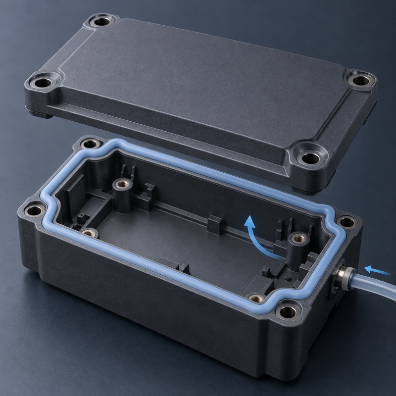
A pressure-decay test can indicate an apparent leak in an LSR overmolded housing even when the silicone seal is not the source of the pressure change. Fixture leakage, temperature drift, changing test volume and relaxation of flexible sealing features can affect the measurement.
However, an unstable result must not automatically be dismissed as a false failure. The assembly may also contain a genuine leakage path through the silicone-to-plastic interface, mating cover, connector opening or another enclosure boundary.
A reliable validation method separates the test system from the product, controls fixture loading and stabilization, and confirms that the test can detect the customer-defined leakage limit under representative conditions.
Why Does Pressure Decay Not Always Mean an LSR Seal Is Leaking?
Consider a compact electronic enclosure with a rigid engineering-plastic housing and a silicone perimeter sealing lip molded directly onto its surface.
The housing is assembled with a mating cover, and the finished unit is connected to an air-leak tester.
During the pressure-decay test, the instrument reports a pressure change that exceeds the agreed threshold.
Does this automatically prove that the molded silicone is defective?
No.
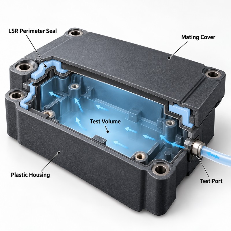
A pressure-decay test measures how pressure changes inside an isolated test volume over time. It does not directly identify the location or physical cause of every pressure change.
A genuine leak is one possible explanation, but the measured volume may also respond to temperature and mechanical loading.
The complete test system may include:
- The internal cavity of the electronic enclosure.
- Connected tubing and pneumatic fittings.
- An adapter or test port.
- The housing and mating cover.
- The integrated silicone seal.
- A mechanical clamping fixture.
- Air trapped in connected spaces.
- Temperature-sensitive measurement components.
If the enclosure, fixture or seal moves during the measurement interval, the effective test volume may change.
If the gas temperature changes after filling, pressure may change without a new physical leak.
If a fixture fitting is not sealed correctly, the instrument may measure leakage that occurs outside the intended product boundary.
This distinction matters when developing a custom LSR overmolded electronic housing gasket. The molded silicone may be a critical part of the sealing system, but its performance must be evaluated in the intended assembled condition.
For products using a rigid thermoplastic frame, plastic with silicone overmolding provides a way to form a localized sealing feature directly onto a suitable plastic substrate.
The correct engineering task is to understand what the test actually measures and determine whether the observed change comes from a product leak, the test system or a combination of both.
What Causes False or Unstable Pressure-Decay Readings?
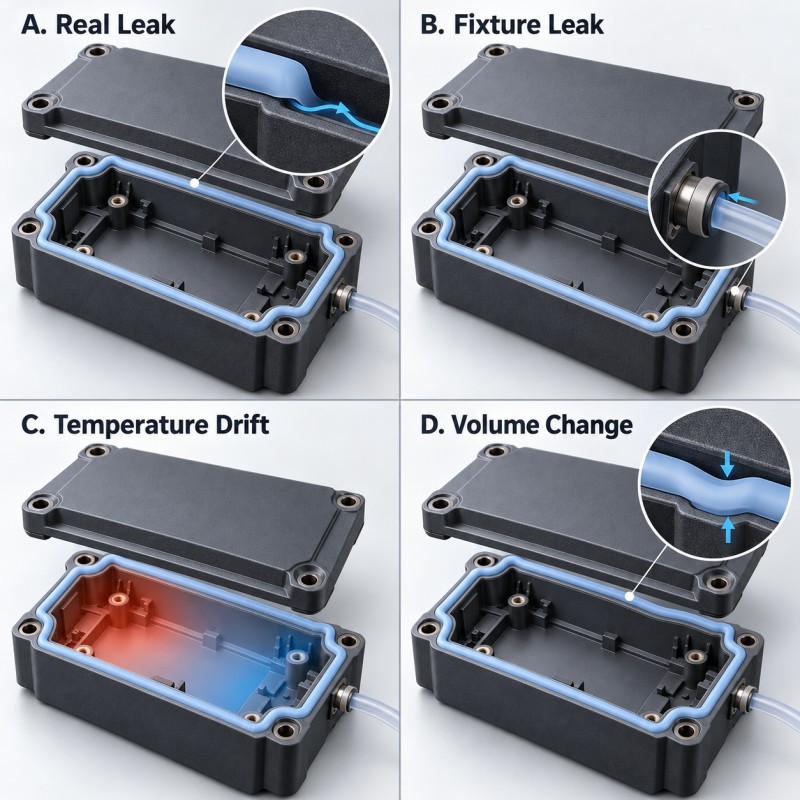
Several measurement effects can resemble leakage during testing of a silicone-overmolded enclosure.
They should be evaluated individually instead of being grouped under the general description of a "bad silicone seal."
1. Gas temperature changes after filling
The test gas may change temperature during pressurization and stabilization.
If the gas cools after the measurement begins, its pressure can decrease even without a corresponding loss of gas.
A housing recently removed from a heated production area may also have a different temperature from the test fixture.
Operator handling, incoming air temperature and the surrounding test environment can influence the result.
2. Flexible silicone and housing movement
Silicone sealing features are deformable.
During pressurization, the mating structure may move slightly, the silicone contact area may redistribute load, or a flexible enclosure wall may deflect.
If the effective volume increases after the supply has been isolated, the pressure can fall without the same amount of gas escaping through a leak.
The effect depends on the actual enclosure and fixture, not simply on the nominal LSR hardness.
3. Fixture and pneumatic connection leakage
A tester may contain hoses, fittings, valves, sealing adapters and temporary connections.
Any of these can introduce a leak independent of the product.
An unstable test-port seal can cause repeated failures even when the housing itself is acceptable.
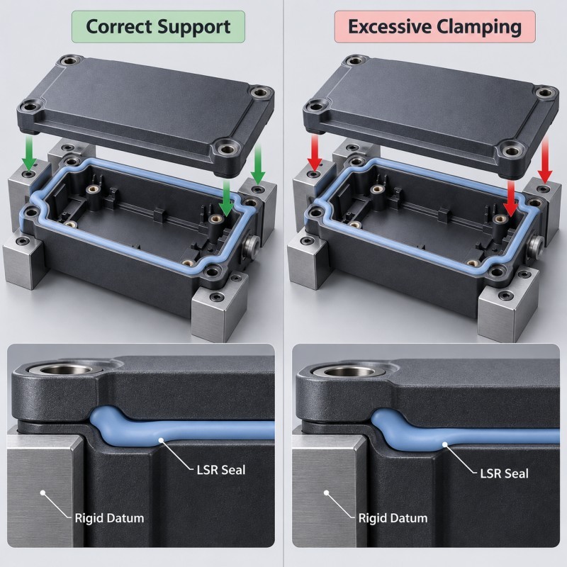
4. Inconsistent fixture clamping
Changing clamping force can alter the position of the rigid housing and the compression of its integrated silicone lip.
A fixture may press the housing beyond its intended assembly condition or fail to seat it completely.
Excessive clamping can also temporarily close a genuine leakage path and produce an apparently acceptable result.
This means incorrect fixture loading can contribute to both false rejection and false acceptance.
5. Unstable connected test volume
Unnecessary tubing, dead-end cavities, adapters and flexible fixture components can change the pressure response.
A test program developed with one fixture volume should not automatically be transferred to a different fixture without evaluation.
6. Insufficient stabilization time
After filling, the gas, fixture and assembly may need time to reach a sufficiently stable measurement condition.
If the test interval begins while temperature or material movement is still changing rapidly, the result may be difficult to interpret.
7. Genuine intermittent leakage
Not every varying result is a measurement error.
A silicone sealing lip may seat differently between assemblies. An interface gap may open only at a specific pressure or temperature. A damaged connector port may leak intermittently.
A variable result should therefore trigger a controlled investigation, not an automatic decision to extend the stabilization timer.
The goal is to separate measurement influences from real leakage while maintaining the required defect-detection capability.
Pressure-Decay Test Symptoms and Possible Causes
| Observed Test Behavior | Possible Cause | First Investigation |
Pressure falls immediately after filling | Gas cooling, unstable volume or actual leakage | Review fill and stabilization profiles |
Result changes with fixture clamping | Seal compression, housing movement or fixture leakage | Control seating position and clamping load |
One fixture fails and another passes | Adapter, fitting or fixture variation | Check reference condition and fixture repeatability |
Warm parts fail more frequently | Temperature difference or temperature-dependent assembly behavior | Control part and test-gas temperature |
| Repeated tests give different results | Fixture seating, test-volume variation or intermittent leak | Repeat under documented conditions |
| Result improves after longer stabilization | Thermal or mechanical settling may be involved | Verify defect detection has not been compromised |
| Pressure change persists on verified equipment | Genuine product leak remains possible | Investigate the assembly leakage path |
How Should the Test Fixture Contact an Overmolded Housing?
The leak-test fixture is part of the measurement system, not simply a device used to hold the product in place.
For an electronic enclosure with an integrated LSR sealing lip, the fixture should reproduce the relevant assembly condition without hiding the leakage path being investigated.
Locate from stable rigid datums
Where practical, support the part using defined plastic housing or carrier datums rather than pressing directly on an uncontrolled silicone surface.
Stable locating features can reduce variation in fixture positioning.
Reproduce the intended final assembly gap
If the silicone seal normally contacts a separate cover, the test arrangement should represent the customer's approved mating geometry.
A fixture that compresses the silicone substantially more than the real product may temporarily close a leakage path.
A fixture that leaves the cover too far away may falsely reject a seal that would be correctly compressed in the final assembly.
Avoid clamping across the defect under investigation
For example, a fixture should not apply a separate temporary seal directly over the silicone-to-plastic edge if the objective is to test that edge.
Such a fixture may create an alternative sealing barrier and conceal the original interface condition.
Account for local housing deformation
Thin plastic walls can deflect under loading.
Fixture support should control unintended movement without introducing excessive stress or changing the approved functional geometry.
Control adapters and connecting volume
Test fittings, pneumatic connections and adapters should be repeatable.
The test system should be checked independently to determine whether its own seals are contributing to the pressure change.
Separate production tooling from test-fixture design
The LSR tool defines the molded silicone geometry, while the leak-test fixture reproduces or evaluates the final sealing condition.
These two systems should use compatible dimensional datums and agreed inspection references.
Early silicone mold design and tooling review can help identify the rigid features, sealing surfaces and silicone boundaries that later require reliable assembly and testing.
A related guide, waterproof silicone seals that pass assembly but fail testing, explains the product-side risks that should be investigated after the measurement system has been assessed.
The leak-test fixture must never be assumed suitable simply because it can hold the part and generate a pass/fail reading.
How Can Engineers Separate a Real Leak From a Test-System Effect?
A practical investigation should proceed from the test system toward the actual silicone sealing boundary.
The following sequence can help reduce unnecessary mold adjustments or material changes.
Step 1: Preserve the original failure evidence
Record the test program, pressure trend, fixture identification, product batch, cavity number where applicable, assembly condition and part temperature.
Do not rely only on the final pass/fail indicator.
The pressure-versus-time trace can provide more information about when the reading changed.
Step 2: Check the test system independently
Use an approved reference condition to evaluate hoses, valves, connections and fixture seals.
The reference method should be capable of revealing a defect in the measurement system itself.
Step 3: Repeat the test under controlled conditions
Record consistent part seating, fixture force, stabilization time, measurement time and ambient conditions.
If repeatability improves, determine which variable changed and why.
An improved reading alone does not prove that a product leak has been eliminated.
Step 4: Compare suitable reference assemblies
Where available, use an approved good assembly and a controlled defective or calibrated-leak reference to assess whether the station can distinguish acceptable and unacceptable conditions.
The reference leak and acceptance threshold must be appropriate to the actual test method.
Step 5: Investigate the actual housing sealing path
When the measurement system is stable, inspect the relevant product interfaces:
- Silicone perimeter contact.
- Silicone-to-plastic bonding or retention.
- Plastic cover fit.
- Connector or cable openings.
- Housing seams.
- Mounting and fastening regions.
- Parting-line or flash-sensitive surfaces.
- Potential hidden fluid paths.
The guide to flash and tolerance control in LSR overmolding describes why small dimensional or flash defects can affect these functional areas.
Step 6: Locate genuine leakage when necessary
Pressure decay is generally an overall measurement rather than a location-specific inspection.
A project-appropriate localization method may be required after confirming a genuine leak. The test method must not damage the component or change the failure mechanism.
Step 7: Confirm the corrective action
If the root cause is the fixture, correct and requalify the test station.
If the root cause is the product, review the relevant silicone geometry, rigid housing, mating structure or manufacturing process.
Both kinds of corrective action require documented verification.
The objective is not to make more parts pass.
It is to distinguish acceptable assemblies from assemblies that do not meet the customer's actual leakage requirement.
What Makes a Pressure-Decay Test Suitable for Production Approval?
A test method that works on a few manually assembled prototypes is not automatically ready for production inspection.
Before approving the test, the customer and relevant manufacturing or test-equipment specialists should define the complete measurement condition.
Define the leakage requirement first
The specification should identify the allowable leakage condition, measurement medium, pressure, relevant exposure condition and acceptance criteria.
A pressure-drop value should not be interpreted without the associated volume, test interval, temperature and measurement method.
Confirm the filling and stabilization stages
The fill and stabilization stages should bring the part and system to a sufficiently stable condition for the intended measurement.
The required time must be established with representative product and fixture conditions.
Confirm measurement sensitivity
The test must reliably distinguish unacceptable leakage from background variation.
Reducing the test pressure, extending the stabilization time or changing the fixture should not be accepted without checking the effect on defect detection.
Review measurement-system variation
Repeatability should be assessed using representative parts, operators and fixture conditions where applicable.
If the result is dominated by fixture variation, the station should not be approved solely because it produces consistent readings on a single reference specimen.
Include realistic part variation
Production parts may vary in:
- Plastic housing flatness.
- Silicone sealing-lip height.
- Insert position.
- Mating-cover dimensions.
- Cavity-to-cavity molding variation.
- Seal surface condition.
- Assembly seating.
The test should remain meaningful across the agreed dimensional limits.
Review environmental and aging requirements
An initial room-temperature pressure-decay test is not a substitute for specified waterproof, thermal, humidity or mechanical validation.
If the customer requires performance after environmental conditioning, the complete assembly should be retested according to that requirement.
Define the response to a failed test
The manufacturing instruction should specify when to repeat a test, how to investigate an abnormal reading and when the component must be rejected.
Uncontrolled retesting until a part passes is not an acceptable quality strategy.
For the broader manufacturing process, validation of silicone overmolded parts before mass production should include the agreed dimensional, interface, sealing, assembly and production-repeatability requirements.
The overmolding supplier can support the discussion of component geometry and manufacturing controls, while the equipment or product owner should approve the final test method and acceptance limits.
LSR Overmolded Housing Pressure-Decay Test Validation Matrix
| Validation Item | Required Engineering Review | Typical Risk |
Test boundary | Identify the exact enclosure and interfaces under test | Wrong sealing path evaluated |
Test pressure | Define project-specific pressure and tolerance | Unrealistic loading or poor sensitivity |
Test volume | Account for part, hoses and fixture cavities | Incorrect interpretation of pressure change |
Gas temperature | Control temperature during measurement | Apparent pressure drift |
Stabilization time | Allow thermal and mechanical effects to settle | False rejection or unstable reading |
Fixture seal | Verify connections and adapters separately | Equipment leak confused with part leak |
Fixture loading | Control seating, gap and clamping force | Genuine leak masked or artificial leak created |
Reference conditions | Use suitable approved reference assemblies | Inadequate defect detection |
Part dimensional variation | Include relevant silicone and rigid-part extremes | Test works only at nominal geometry |
Measurement repeatability | Evaluate representative station and loading variation | Unreliable pass/fail decisions |
| Failure localization | Confirm actual path when a genuine leak is indicated | Wrong component corrected |
| Environmental validation | Apply the customer's required conditioning | Initial pass mistaken for service qualification |
| Production monitoring | Document settings, maintenance and responses | Test drift between production periods |
What Should Buyers Include in a Leak-Test-Related LSR Overmolding RFQ?
For an electronic housing that requires an integrated silicone seal and pressure-based validation, the initial RFQ should describe the complete assembly and the intended test method.
A useful engineering package includes:
1. The 2D drawing and 3D CAD model of the plastic housing.
2. The plastic grade and any relevant material or surface-treatment information.
3. The required silicone coverage map.
4. The proposed LSR material or functional material requirements.
5. The complete mating-cover or enclosure drawing.
6. The intended assembly gap and fastening or locking method.
7. Critical sealing surfaces and no-silicone areas.
8. Connector, cable and other openings in the protected housing.
9. The actual leakage or ingress requirement.
10. The proposed pressure-decay test specification, if available.
11. The intended test pressure, gas, timing and acceptance method.
12. Known temperature or fixture-related testing concerns.
13. Any available pressure curves or failure reports.
14. Prototype quantity, annual demand and desired validation sequence.
If the project has already experienced unstable leak-test results, provide information on which assemblies failed, whether the same parts produced repeatable results and what changes were made during retesting.
Avoid sending only a statement such as "IP68 silicone gasket required."
The engineering team needs to know whether the test is intended to verify an external environmental seal, an internal pressure boundary or another specific product function.
The customer's final ingress requirement and the production pressure-decay method may be related, but they are not interchangeable unless the correlation has been established.
A clear project specification allows the silicone molding supplier, product engineer and leak-test specialist to work from the same functional boundary and approval criteria.
Frequently Asked Questions
Can a good LSR seal fail a pressure-decay test?
Yes. A correctly manufactured seal may be associated with an apparent test failure if the fixture leaks, the gas temperature changes, the test volume is unstable or flexible parts continue moving during measurement. However, a real product leak must still be ruled out through a controlled investigation.
Can silicone deformation create an apparent pressure drop?
Potentially. If the effective test volume increases as a flexible seal, housing or fixture relaxes under pressure, the measured pressure may decrease even without a corresponding product leak. The significance of the effect depends on the complete part and test arrangement.
Will increasing stabilization time always solve false leak results?
No. Stabilization may reduce some temperature-related or mechanical transients, but it cannot repair a leaking fixture or defective product. Any change to the test program should be validated to ensure that unacceptable leaks remain detectable.
Does passing a pressure-decay test prove IP67 or IP68 performance?
Not automatically. A pressure-decay test and an enclosure ingress-protection test evaluate performance under their own defined conditions. A correlation must be established if one method is intended to serve as a production screening test for a separate ingress requirement. The final assembly must meet the customer's applicable validation standard.
Can SiliconePlus help with pressure-decay test failures?
SiliconePlus can review the manufacturability of custom LSR overmolded components, including silicone coverage, plastic substrate geometry, sealing-lip dimensions, insert positioning and functional interfaces. The customer's quality or leak-test specialist should verify the test equipment, method and acceptance criteria. Project-specific test capability should be confirmed during the RFQ review.
Conclusion
A pressure-decay result should not be interpreted without understanding the complete test system.
For an LSR overmolded electronic housing, pressure change can be influenced by a genuine leakage path, fixture condition, temperature, effective test volume and movement of flexible or rigid components.
The correct engineering approach separates three questions:
- Is the silicone-overmolded housing manufactured according to the approved drawing?
- Does the complete assembly meet the specified sealing requirement?
- Can the selected measurement method distinguish acceptable and unacceptable assemblies repeatably?
A good test process should not reject conforming parts because of uncontrolled fixture or environmental effects.
Equally importantly, it must not accept leaking parts because excessive clamping or an unsuitable fixture masks their defects.
Manufacturing DFM, assembly design and leak-test development should be coordinated before production approval.
For OEM engineers and sourcing teams, the most useful outcome is a defined, repeatable test method that reflects the actual product requirement—not simply the lowest possible pressure-drop reading.
Discuss Your LSR Overmolded Housing Project With SiliconePlus
Are you developing a plastic electronic housing that requires an integrated silicone perimeter seal?
SiliconePlus supports custom LSR overmolding projects involving rigid plastic carriers, precision silicone sealing features and drawing-based manufacturing requirements.
Our team can review the proposed silicone coverage, substrate materials, seal geometry, functional keep-out areas, insert positioning, tooling feasibility and component inspection requirements.
If your project includes pressure-decay testing, please also share the relevant assembly drawing, test boundary, pressure specification, acceptance criteria and any existing failure information.
These details help distinguish component manufacturability questions from matters that need review by the customer's testing or equipment specialists.
For a project evaluation, please provide your 2D or 3D files, mating-part information, silicone requirements, functional sealing target, expected quantity and available test records.
Please contact SiliconePlus to discuss your custom LSR overmolding and electronic housing sealing requirements before tooling.