Why Can Water Wick Through a Cable After LSR Overmolding?
- Share
- publisher
- SiliconePlus Engineering Team
- Issue Time
- Oct 19,2026
Summary
Why can an LSR-overmolded cable entry still admit moisture? External silicone-to-jacket sealing cannot automatically stop water traveling within stranded conductors or other internal cable paths. This guide explains separate leakage mechanisms, engineering responsibilities, diagnostic tests and RFQ requirements for custom cable feedthrough seals.
Answer Excerpt
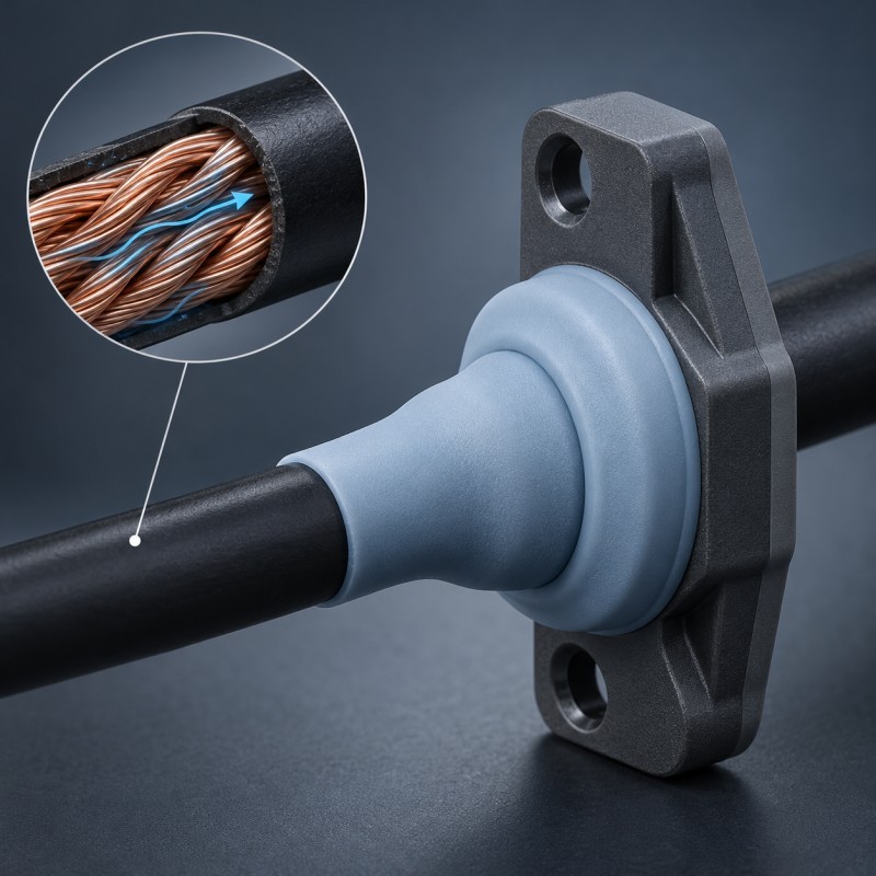
Water can sometimes travel through a cable after LSR overmolding because an external silicone seal and the cable's internal water-blocking system protect different leakage paths. LSR molded around a cable jacket or plastic carrier may help seal the cable-entry interface, but it does not automatically fill gaps between stranded conductors, internal cable layers or an unprotected cable termination. Engineers should distinguish leakage around the outer jacket from longitudinal water migration inside the cable, then specify the appropriate cable construction, overmold geometry and assembly-level tests before tooling.
How Can a Cable Leak When the Outside Silicone Seal Looks Intact?
Consider an electrical cable passing through a rigid plastic enclosure.
A localized liquid silicone rubber (LSR) feature is molded around the cable jacket and a defined area of the plastic carrier. The finished overmold appears continuous, the cable remains correctly positioned, and the external silicone edge shows no obvious damage.
However, moisture is discovered near the electrical termination after environmental testing.
It is tempting to conclude that the silicone did not bond to the cable jacket. That may be one possible cause, but it is not the only explanation.
A cable is a multi-material assembly, not a solid rod.
Depending on its construction, it may contain:
- An outer jacket or individual wire insulation.
- One or more insulated conductors.
- Stranded copper or other conductive material.
- Fillers, shielding, drain wires or reinforcement.
- Internal gaps between individual layers.
- Crimped or soldered terminations at one or both ends.
Water may enter at a location outside the visible overmold and move along an internal path that the external silicone never contacts.
For example, moisture reaching an exposed cable termination may migrate through small spaces between conductor strands. The external LSR layer can remain intact while water travels inside the wire.
This is why cable-entry sealing should be evaluated as a complete assembly function.
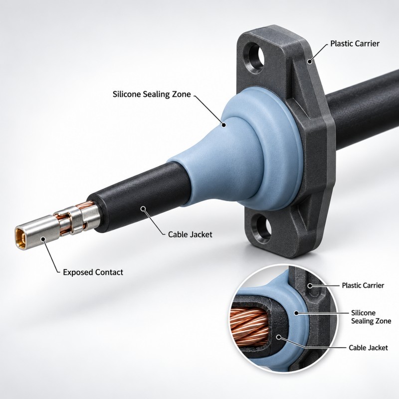
SiliconePlus offers a custom LSR overmolded cable feedthrough seal for projects involving cable entries and engineering-plastic carriers. The product illustrates controlled silicone coverage around the exterior of a cable and its supporting structure.
For the broader housing and feedthrough design, review the liquid cooling cable grommet design guide.
Neither an external overmolded seal nor a separately assembled grommet should be described as a complete internal conductor water-blocking solution unless that function has been specifically engineered and validated.
What Are the Three Main Moisture Paths in a Cable Feedthrough?
A cable feedthrough failure should be investigated by tracing the actual path from the wet region to the protected electrical area.
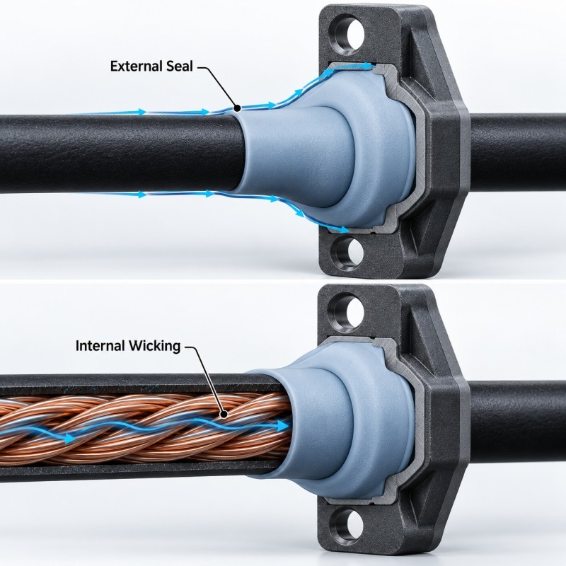
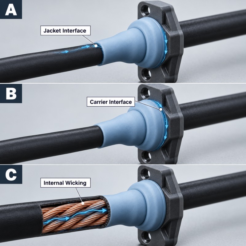
Three fundamentally different routes should be considered.
Path 1: Leakage around the outside of the cable jacket
Water may travel along a clearance between the cable jacket and the overmolded silicone.
Potential contributing factors include:
- Incompatible jacket and LSR materials.
- Poorly controlled surface condition.
- Insufficient silicone contact or retention.
- Local cable movement during molding.
- An incomplete or damaged silicone boundary.
- Variation in cable outside diameter.
- Mechanical stress after assembly.
This is an external interface problem. The overmold design, cable surface, insert support and sealing arrangement must be reviewed.
Path 2: Leakage around the rigid carrier or enclosure opening
Even when the silicone contacts the cable correctly, moisture may pass between the silicone structure and the plastic carrier or through an adjacent housing interface.
A molded component may require more than one functional sealing boundary.
The designer should identify the complete path around the carrier, including:
- Silicone-to-plastic transition.
- Housing opening and mating geometry.
- Seal compression where applicable.
- Housing deformation.
- Molded silicone discontinuities.
- Separate assembly joints.
This is an assembly-interface problem, not necessarily a cable-jacket problem.
Path 3: Longitudinal migration within the cable
Moisture may enter through a remote damaged section, an exposed termination or a cable-end interface and move through internal spaces.
Possible paths include gaps:
- Between strands of a conductor.
- Between conductor insulation and internal layers.
- Along certain shielding or filler structures.
- Within other unfilled regions of the cable construction.
The exact path depends on the cable design.
This is a cable-construction and termination problem. Adding more silicone around an intact outside jacket does not automatically close internal spaces that the LSR cannot reach.
The sealing design should identify which path each barrier is intended to interrupt.
External Sealing Versus Internal Cable Water Migration
| Moisture Path | Typical Location | Primary Engineering Responsibility | Key Validation |
| Cable jacket interface | Between LSR and exterior cable jacket | Overmold design, material compatibility and cable surface | Defined exterior seal / assembly test |
| Carrier or housing interface | Around plastic carrier and enclosure opening | Silicone geometry and mating assembly | Full housing leak-path test |
| Longitudinal conductor path | Inside cable construction or between wire strands | Cable construction, termination and water-blocking design | Dedicated longitudinal water-migration assessment |
Does LSR Overmolding Stop Capillary Water Movement Inside Stranded Wires?
Not automatically.
Capillary action can occur when liquid enters narrow connected spaces, including some gaps within stranded conductors.
The presence and extent of water migration depend on the wire construction, wetting behavior, path geometry, exposure conditions and pressure differences.
A silicone feature molded around the exterior cable jacket does not normally reach the conductor strands beneath intact insulation.
Therefore, the following two requirements must be specified separately:
External sealing requirement: Prevent unwanted moisture ingress across the cable-jacket, overmold and housing interfaces.
Longitudinal blocking requirement: Restrict moisture migration through the internal cable construction when water enters an exposed or damaged cable region.
A cable assembly may require both, but one test should not be used as evidence for the other without a defined relationship.
For applications requiring internal water blocking, potential solutions may involve cable constructions with purpose-designed blocking materials, sealed terminations or other qualified internal barriers.
These are not universal capabilities of every LSR overmolding operation.
The cable supplier, connector supplier and overmolding manufacturer may need to coordinate the solution.
It is also important to distinguish an independently assembled wire seal from a molded-in LSR cable overmold. The first generally seals around the outside of an insulated wire inside a connector cavity. The second is formed directly onto an approved cable or carrier region.
For an overview of external connector sealing locations, see Where Should Automotive Connectors Be Sealed? Face, Housing Perimeter and Wire Entry.
Neither component automatically guarantees longitudinal watertightness through the conductor itself.
Which Cable and Carrier Details Must Be Defined Before Tooling?
LSR overmolding should be developed around the actual cable and rigid carrier, rather than an assumed nominal cable diameter.
A drawing showing only the final outer silicone shape does not provide enough information to evaluate cable-entry sealing.
1. Confirm the real cable construction.
Request the exact cable drawing or specification, including:
- Cable type and supplier.
- Outer jacket or wire insulation material.
- Outside diameter and tolerance.
- Number and type of conductors.
- Relevant stranded-conductor construction.
- Shielding, filler and reinforcement details.
- Cable-end and termination arrangement.
- Any specified longitudinal water-blocking features.
Not every item will affect the silicone cavity directly, but these details help establish the complete leakage-path map.
2. Confirm what the silicone actually contacts.
The LSR may contact a cable jacket, a molded plastic carrier or a defined combination of both.
The engineering drawing should identify each substrate and the intended silicone coverage boundary.
Adhesion to a cable jacket must not be assumed from its generic material name. Actual material grade, additives, surface condition and processing exposure matter.
3. Control cable positioning during molding.
A flexible cable can move, bend or rotate during loading and mold closing.
Movement can change the local silicone thickness or move a sealing feature away from its intended position.
Locating features should support the rigid carrier and cable without crushing insulation or exposing electrical conductors.
4. Define the cable exit and bending zone.
Sealing and mechanical strain relief may share one integrated overmolded structure, but they remain different functional requirements.
A transition that prevents an initial exterior leak may still suffer damage if the cable is repeatedly bent at an unsupported edge.
For a relevant product structure, review the custom LSR overmolded cable strain relief for automotive wire harness.
5. Preserve functional no-silicone regions.
Mating terminals, crimp contacts, electrical test points, connector cavities, required grounding surfaces, locating holes and other functional openings must remain accessible according to the drawing.
Silicone should not flow into conductor terminations merely because the project requires moisture protection.
6. Review the actual assembly boundary.
The cable-to-silicone interface is only one part of the system.
The design should identify where the rigid carrier meets the enclosure, whether a compressed seal is needed, which surface supports it and where water could bypass the intended barrier.
A completed overmold must be evaluated in the final assembly rather than judged only from a product photograph.
What Can the Overmolding Manufacturer Control and What Requires Cable Supplier Support?
A reliable development process separates the manufacturing variables controlled during LSR overmolding from the cable properties defined upstream.
This distinction is especially important when a customer requests a "waterproof overmolded cable" without identifying the intended leakage boundary.
What the overmolding manufacturer can evaluate
For a suitable cable and carrier structure, the silicone overmolding process can address:
- Local silicone coverage geometry.
- Cable and insert positioning.
- Compatibility of selected LSR and substrate materials.
- Mold shut-off at functional boundaries.
- Silicone-to-carrier or silicone-to-jacket retention.
- Local sealing-lip design where applicable.
- Rigid carrier support.
- Strain-relief geometry.
- Dimensional and appearance inspection.
- Repeatability of the agreed molding process.
SiliconePlus provides liquid silicone injection molding for custom components designed around suitable inserts and defined engineering requirements.
However, a conforming molded part should not be treated as proof that the complete cable is internally water blocked.
What requires cable or termination expertise
Depending on the architecture, the cable manufacturer or termination specialist may be responsible for:
- Internal conductor geometry.
- Water-blocking materials inside the cable.
- Shielding and filler construction.
- Cable-end sealing.
- Crimp or solder termination design.
- Compatibility of any internal sealant with the electrical assembly.
- Longitudinal water-migration qualification.
These features must not be assigned to the external LSR overmolding process without an explicit and validated scope of work.
What the complete assembly team must confirm
The final equipment manufacturer is typically responsible for specifying:
- The expected source of water exposure.
- The complete protected electrical volume.
- Pressure, immersion or spray requirements where applicable.
- Mechanical pull and bend conditions.
- Environmental aging requirements.
- Acceptance limits and test methods.
For the mechanical side of cable protection, the related strain relief design for LSR overmolded cable parts explains why cable-root geometry and actual bending loads must also be evaluated.
A coordinated system can require a qualified cable construction, an appropriate external silicone overmold and a properly sealed final enclosure.
The correct combination depends on the application rather than a universal promise of waterproof performance.
Cable Water-Blocking Responsibility Matrix
| Design or Test Activity | Primary Party to Consult | Expected Output |
External silicone geometry | LSR overmolding manufacturer | Coverage map and manufacturable geometry |
Cable jacket compatibility | Cable supplier + LSR manufacturer | Agreed substrate and material qualification |
Mold positioning and shut-off | LSR tooling / process team | Insert support and no-silicone boundary |
Internal conductor water blocking | Cable supplier | Cable construction and longitudinal test evidence |
| Termination sealing | Connector or termination supplier | Qualified termination boundary |
| Enclosure interface | Product development team + seal manufacturer | Complete interface and assembly design |
| Final ingress requirement | Product owner / test team | Acceptance criteria for the finished assembly |
How Can Engineers Identify Whether Water Entered Around the Seal or Through the Cable Core?
A useful failure investigation begins with a leakage-path hypothesis, not an immediate change to the silicone material.
Different failure modes can produce moisture near the same terminal while requiring different corrective actions.
Step 1: Document the finished assembly.
Record the cable supplier and batch, cable jacket material, silicone overmolding batch, carrier geometry, enclosure configuration and the original environmental test.
Confirm whether the cable ends and remote terminations were exposed during testing.
Step 2: Inspect the external silicone and carrier interfaces.
Look for visible silicone separation, jacket damage, gaps, housing distortion, flash interference and incorrect seal compression.
These observations may indicate a local interface defect, but an intact appearance does not prove that every path is sealed.
Step 3: Define controlled investigation paths.
Where the component architecture allows, compare specimens that isolate the external feedthrough with specimens that specifically expose an approved cable end.
The isolation method must not create an artificial leakage path or unintentionally block the route being investigated.
For example, protecting a remote cable termination during one trial and exposing it during a separate controlled trial may help identify whether end-entry is relevant.
The test design should be approved by the customer's engineering and validation team.
Step 4: Inspect internal cable construction when justified.
A suitably prepared destructive section may reveal gaps, damaged insulation, internal pathways or evidence of moisture.
The inspection should distinguish water outside the jacket from water inside the cable construction.
If dye or another tracer is used, its compatibility and possible influence on wetting must be considered.
Step 5: Compare results against the original requirement.
An external jacket interface that passes its defined test does not necessarily demonstrate conductor longitudinal watertightness.
Likewise, a failed complete-assembly test does not, by itself, prove that the overmolding supplier caused the defect.
Failure reports should state the observed moisture location, the suspected path, the evidence and any remaining uncertainty.
Step 6: Validate the corrective action at the actual failed boundary.
If the failure is external, the team may need to revise silicone contact, material compatibility, carrier geometry or cable positioning.
If the failure is internal, an appropriate cable construction or termination-sealing solution may be required.
Changing the outer silicone hardness or increasing the overmold length should not be the default response to confirmed conductor-core wicking.
Which Tests Should Be Included in a Cable Overmolding Validation Plan?
The validation plan should test the function of each agreed sealing boundary and then confirm the complete assembly.
No single generic test can establish every external and internal cable water-blocking requirement.
External overmold inspection
Verify cable position, coverage length, silicone boundary, visible defects, carrier fit and functional no-silicone zones.
Where required, inspect the hidden interface through an approved sample-section method.
Material and interface evaluation
Confirm that the actual cable jacket, carrier substrate and LSR formulation can tolerate the selected molding process.
Where adhesion is a functional requirement, define an applicable test method and failure acceptance criteria.
Assembly-level water-ingress test
The customer should define the exposure method, water or test medium, duration, temperature, pressure conditions where relevant and the permitted result.
The test fixture and cable-end protection must be documented so the intended leakage paths are known.
Longitudinal water-migration evaluation
If the cable must resist moisture traveling inside its own construction, specify a dedicated cable or termination-level test.
The responsible cable supplier should confirm the applicable method, sample preparation, exposed end conditions and acceptance limit.
Do not assume that an external enclosure IP test measures longitudinal conductor blocking.
Mechanical loading
Where cables experience bending or pulling, assess whether mechanical loads change the external sealing interface or cable-root transition.
Mechanical loading may need to occur before the environmental test rather than after it.
Environmental conditioning
The final assembly may require thermal cycling, humidity exposure or other defined conditions followed by sealing and functional checks.
These tests must be selected from actual project requirements, not from an unsupported universal specification.
Electrical function
Depending on the cable and equipment, check continuity, required insulation properties and contact integrity before and after relevant environmental exposure.
Pilot-production consistency
Evaluate representative production cable and carrier batches, not only hand-selected prototype inserts.
Record changes in cable diameter, material supplier, processing or termination construction that could influence the approved design.
The final report should identify which sealing functions were tested and which remain outside the approved scope.
Cable Feedthrough and Longitudinal Water-Blocking Validation Matrix
| Validation Item | Main Question | Evidence to Collect |
Cable / carrier dimensional check | Is the external interface repeatable? | Measurements and inspection records |
Jacket and LSR compatibility | Is the selected material combination suitable? | Approved material-specific qualification |
Silicone-to-substrate interface | Is retention or bonding adequate? | Project-defined interface test |
External ingress | Does water bypass the overmold or carrier seal? | Controlled assembly-level exposure test |
Internal conductor wicking | Can water migrate within the cable? | Separate longitudinal blocking test |
Pull and bending | Does mechanical loading compromise sealing? | Before-and-after test results |
| Thermal or humidity exposure | Does environmental conditioning affect the interface? | Project-specific conditioning results |
| Electrical performance | Does the assembly remain functional? | Required electrical inspection |
| Production repeatability | Are approved results reproducible? | Representative lot and process records |
Frequently Asked Questions
Can LSR overmolding make any stranded cable completely waterproof?
No. LSR overmolding can form a localized external sealing structure when the cable and substrate are suitable, but it does not automatically block water migration through internal conductor strands or cable layers. Complete waterproof performance depends on the cable construction, terminations, overmold, enclosure and project-defined validation.
Why can moisture appear at a terminal when the silicone seal is not damaged?
Moisture may have entered through a remote cable end, damaged insulation or another internal pathway and traveled toward the terminal. External jacket leakage is another possibility. The actual route should be identified through a controlled investigation before the silicone design is changed.
Is a separately molded single wire seal the same as direct LSR cable overmolding?
No. A separate wire seal is manufactured as an independent part and assembled around an insulated wire, usually within a connector cavity. Direct LSR cable overmolding forms silicone onto a specified cable or carrier region during the molding process. Both may provide external sealing functions, but their manufacturing and assembly requirements are different.
Does a successful enclosure IP test prove longitudinal cable water blocking?
Not necessarily. An enclosure ingress test evaluates the assembled product under defined conditions. It may not challenge the internal cable pathway unless the test setup specifically includes and exposes that path. A separate longitudinal water-migration requirement and method may be necessary.
What information should be provided to an LSR overmolding manufacturer?
Provide the 2D or 3D assembly drawing, actual cable sample, jacket material, cable construction, plastic carrier information, silicone coverage map, protected electrical regions, expected exposure, bending and pulling requirements, water-ingress specification, any longitudinal water-blocking requirement, validation criteria and estimated quantity.
Conclusion
A cable feedthrough should not be called waterproof simply because a continuous layer of silicone surrounds its exterior.
The complete design must distinguish three potential routes: moisture around the cable jacket, moisture around the carrier or housing interface, and moisture traveling inside the cable construction.
Localized LSR overmolding can be an appropriate manufacturing method for defined exterior sealing and strain-relief functions.
However, internal conductor water blocking is a separate engineering requirement. It may depend on specialized cable construction, termination design and qualification methods outside the scope of ordinary external overmolding.
The most effective DFM approach is to identify the actual leakage path, assign each sealing boundary to the responsible design or manufacturing process, and validate the complete assembly under the customer's conditions.
For engineers and sourcing teams, a precise specification is more useful than a general request for a "fully waterproof silicone cable."
Define where water could enter, where it must be stopped, and how the result will be verified before committing to tooling.
Discuss Your Custom LSR Cable Feedthrough Project With SiliconePlus
Are you developing an electrical cable entry, sensor wire transition or rigid-plastic carrier that requires integrated silicone sealing and strain relief?
SiliconePlus supports custom LSR overmolding for suitable cable, connector and engineering-plastic insert structures.
Our engineering team can review the proposed silicone coverage area, cable jacket and carrier materials, functional keep-out zones, insert positioning and exterior sealing requirements before tooling.
If your project also specifies longitudinal water blocking inside the cable, please identify that requirement separately so the complete cable and termination design can be evaluated with the responsible suppliers.
For an initial DFM review, provide:
- 2D or 3D assembly drawings.
- Cable samples and jacket specifications.
- Cable construction and termination details.
- Rigid carrier or housing material.
- Required LSR coverage and no-silicone zones.
- Exterior and internal water-blocking requirements, if applicable.
- Assembly and environmental test conditions.
- Expected prototype and production quantities.
Please contact SiliconePlus to discuss the manufacturability of your custom LSR overmolded cable feedthrough or strain-relief component.