How Should an LSR Sealing Collar Be Designed Around EV Charging Inlet Terminals?
- Share
- publisher
- SiliconePlus Engineering Team
- Issue Time
- Aug 18,2026
Summary
An LSR sealing collar around an EV charging inlet terminal should seal the terminal-to-housing interface while keeping the electrical mating contact completely exposed. Reliable design depends on silicone coverage position, collar geometry, terminal centering, housing interference, metal surface condition, mold shut-off and tolerance stack-up. The final structure should be validated in the actual charging-inlet housing rather than only as a loose overmolded terminal.
Answer Excerpt
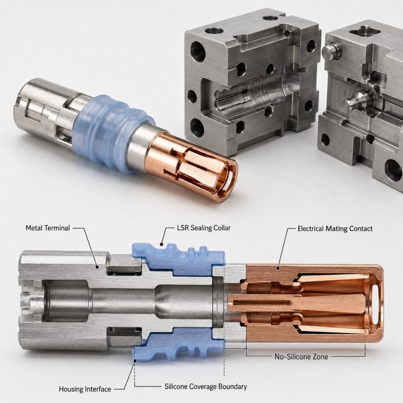
An LSR sealing collar around an EV charging inlet terminal should create a controlled seal between the metal terminal and its surrounding housing while keeping the electrical mating contact completely exposed. The sealing collar should be designed together with terminal position, silicone coverage, housing bore geometry, interference, metal surface condition, mold shut-off and dimensional tolerance. The final seal should be validated inside the real charging-inlet assembly rather than only on a loose terminal.
An EV charging terminal performs two different functions in the same component.
The exposed metal section must provide reliable electrical mating, while another section of the terminal may require sealing, insulation and environmental protection where it passes through the connector or charging-inlet housing.
This makes the silicone coverage boundary critical.
The LSR should not simply cover as much metal as possible.
It should form a controlled sealing collar only around the section required by the assembly design while leaving the electrical contact, mating surface and other specified functional metal areas completely exposed.
For an actual product example, review our custom LSR overmolded EV charging inlet terminal seal.
What Does the LSR Sealing Collar Actually Seal?
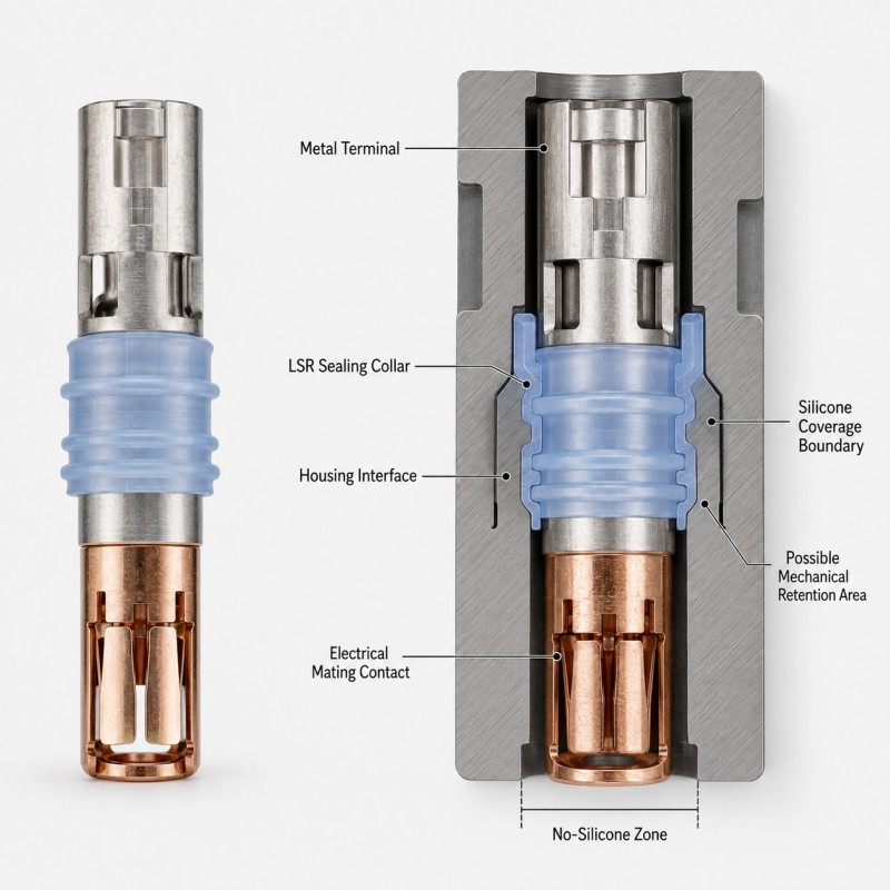
The overmolded sealing collar is normally designed to control the interface where the metal charging terminal passes through or interfaces with another component in the charging connector or inlet.
Depending on the assembly, the collar may support:
• Terminal-to-housing sealing
• Moisture-ingress protection
• Dust protection
• Electrical insulation around non-contact metal areas
• Vibration damping
• Stable seal positioning
• Mechanical retention around the terminal
• Controlled interface dimensions
The important point is that the silicone collar is not the complete charging-inlet seal by itself.
Its performance depends on how the collar contacts the surrounding plastic housing or mating interface after assembly.
A sealing collar that looks perfect on the metal terminal may still leak if:
• The housing bore is too large
• The terminal is off-center
• The collar height is too low
• The collar is excessively compressed
• The housing is warped
• The sealing surface is interrupted
• The final assembly position changes
The collar should therefore be designed from the assembled interface backward, not from the loose terminal outward.
Which Areas of the Charging Terminal Must Remain Exposed?
The electrical mating section of the charging terminal must remain completely clean and accessible after LSR overmolding.
Depending on the terminal design, protected functional areas may include:
• Electrical mating contact
• Conductive contact surface
• Plated electrical area
• Contact spring area
• Terminal insertion area
• Crimp or weld area
• Threaded electrical connection
• Measurement point
• Locating surface
• Assembly datum
These areas should be defined as functional no-silicone zones before tooling.
The silicone coverage boundary should not be controlled only by visual appearance.
The drawing should define where the silicone starts and stops relative to a stable terminal datum.
If the mold shut-off opens or the terminal shifts during injection, even a thin silicone film may extend into the electrical mating region.
For a broader DFM method, review how no-silicone zones should be designed in LSR overmolding.
How Should the Sealing Collar Geometry Be Designed?
The sealing collar should be designed according to the surrounding housing geometry and the direction in which the silicone is compressed after assembly.
Important geometry includes:
• Collar outer diameter
• Collar height
• Silicone wall thickness
• Sealing-lip profile
• Root radius
• Transition to the metal terminal
• Distance from the electrical contact area
• Mechanical-retention location
• Housing interference
• Available assembly space
Collar Outer Diameter
The outside diameter controls how much interference is created when the terminal seal enters the surrounding housing.
Too little interference may leave an unstable sealing contact.
Too much interference may increase insertion force, distort the silicone or make terminal installation difficult.
Collar Height
The seal should have enough axial length to create a stable interface with the housing.
A collar that is too short may become sensitive to terminal movement or housing tolerance.
Wall Thickness
The silicone around the metal terminal should be thick enough to mold and demold consistently without becoming unnecessarily bulky.
Root Radius
The transition between the sealing collar and surrounding silicone should avoid sharp stress concentrations.
Electrical Clearance
The sealing geometry must stop before the electrical mating area so that normal connector function remains unaffected.
How Does the Metal Terminal Affect the LSR Sealing Collar?
The metal terminal is both the functional electrical component and the insert that supports the overmolded silicone.
Its condition can affect the final sealing collar.
Important terminal variables include:
• Metal alloy
• Plating
• Surface cleanliness
• Oxidation
• Terminal diameter or thickness
• Flatness
• Local steps
• Retention holes or grooves
• Insert-position tolerance
If the terminal dimension changes, the final silicone thickness around it also changes.
If the metal surface contains oil, oxidation or inconsistent plating, the silicone-to-metal interface may become less repeatable.
Where the design relies on mechanical retention, the terminal may include a groove, window, through-hole or other feature that allows the cured silicone to lock physically around the insert.
The retention feature must still be positioned away from the active electrical contact area.
For incoming-metal control, review how metal inserts should be prepared before LSR overmolding.
How Should the Sealing Collar Fit the Plastic Housing?
The charging terminal seal should be evaluated together with the plastic housing bore or sealing interface that compresses the LSR collar.
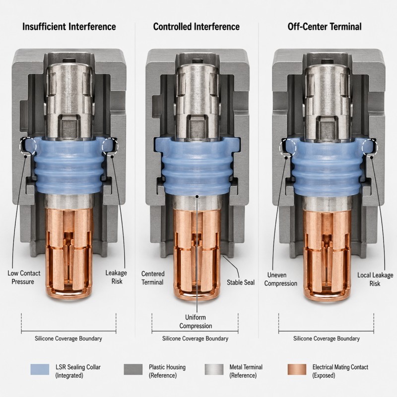
Three conditions are especially important.
Insufficient Interference
If the housing opening is too large relative to the silicone collar, contact pressure may become too low.
Possible results include:
• Local sealing gaps
• Leakage at tolerance extremes
• Greater sensitivity to terminal movement
• Unstable results after vibration or thermal cycling
Controlled Interference
The preferred condition creates continuous silicone contact around the terminal without excessive distortion.
The collar remains centered and maintains a repeatable sealing band around the housing interface.
Off-Center Compression
If the terminal is tilted or shifted, one side of the collar may be compressed heavily while the opposite side receives too little compression.
Possible results include:
• Uneven sealing pressure
• Local leakage path
• Assembly interference
• Collar deformation
• Different leak-test results between samples
Terminal centering is therefore part of seal design rather than only an insert-loading issue.
Why Must Terminal-to-Housing Tolerance Stack-Up Be Reviewed?
The terminal sealing collar cannot be designed from nominal dimensions alone.
The actual compression may be affected by:
• Metal terminal dimensions
• Terminal-position tolerance
• Silicone collar outer diameter
• Silicone collar height
• LSR dimensional variation
• Plastic housing bore diameter
• Housing position
• Housing warpage
• Mold-cavity variation
• Final assembly position
At minimum, the DFM review should check:
Minimum Sealing Condition
The collar is at its smaller condition while the surrounding housing opening is at its larger condition.
The seal must still maintain continuous functional contact.
Nominal Condition
The terminal, silicone collar and housing are near their nominal dimensions.
This is useful for initial design review but should not be the only condition tested.
Maximum Interference Condition
The silicone collar is at its larger condition while the housing opening is at its smaller condition.
The assembly must still be possible without excessive silicone deformation, terminal movement or unacceptable insertion force.
A design that works only at nominal CAD dimensions may become unstable in mass production.
EV Charging Terminal Sealing Collar DFM Checklist
DFM Item | What Engineers Should Confirm | Main Risk |
Electrical contact | Exposed mating area is clearly defined | Silicone blocks electrical function |
Silicone coverage | Start and stop positions are dimensioned | Coverage varies |
Terminal material | Alloy, plating and surface condition are confirmed | Interface inconsistency |
Collar outer diameter | Housing interference is reviewed | Leakage or high insertion force |
Collar height | Sufficient sealing length is available | Unstable contact |
Wall thickness | Silicone can fill and demold consistently | Tear or short shot |
| Terminal centering | Insert is supported accurately | Uneven compression |
Housing bore | Diameter, flatness and position are available | Seal designed without mating data |
| Mechanical retention | Lock geometry matches load direction | Collar movement or peel |
| Mold shut-off | Electrical area remains protected | Silicone contamination |
| Validation | Leak, assembly and electrical checks are defined | Part looks good but system fails |
The silicone mold design and tooling review should confirm the terminal datum, silicone coverage boundary, sealing-collar geometry, mechanical retention, mold shut-off, gate, venting and final housing interface before mold steel is finalized.
How Should an EV Charging Terminal Seal Be Validated?
The overmolded terminal should be validated both as a molded component and inside the final charging-inlet assembly.
Recommended validation includes:
1. Electrical Contact Exposure Inspection
Confirm that silicone has not entered the electrical mating area, plated contact surface or other protected functional zones.
2. Terminal Position Inspection
Check terminal centering, tilt, rotation and final silicone position.
3. Collar Dimensional Inspection
Measure collar outer diameter, height, silicone boundary and other critical sealing dimensions.
4. Assembly Test
Install the terminal into the actual or representative plastic housing and confirm that the collar does not roll, tear or create excessive insertion force.
5. Leak Testing
Complete the agreed air-leak, pressure-decay, immersion or other system-specific sealing test after assembly.
6. Pull or Retention Testing
Where required, confirm that the overmolded silicone and mechanical-retention structure remain stable under the expected terminal load.
7. Thermal and Vibration Validation
For automotive applications, repeat sealing and functional inspection after the agreed environmental and mechanical conditions.
8. Pilot-Production Validation
Compare multiple mold cavities, consecutive cycles and realistic incoming terminal lots before mass-production approval.
How SiliconePlus Supports EV Charging Terminal Overmolding
SiliconePlus supports custom EV charging terminal overmolding projects from terminal and assembly review through tooling, sampling, inspection and mass production.
Project support can include:
• Metal terminal and plating review
• Silicone coverage definition
• Electrical no-silicone-zone review
• Sealing-collar DFM
• Terminal-positioning design
• Metal-to-silicone interface review
• Mechanical-retention design
• Mold shut-off review
• Gate and venting analysis
• Precision mold development
• LSR injection molding
• Dimensional and interface inspection
• Assembly and leak-test support
• Pilot-production validation
Specific collar dimensions, interference, material, bonding, waterproof requirements and electrical acceptance criteria should always be confirmed according to the actual charging terminal, plastic housing and customer validation method.
FAQ
Should the Entire EV Charging Terminal Be Covered with Silicone?
No. The electrical mating area and other specified functional metal surfaces must remain exposed. Silicone should cover only the sealing, insulating or retention area defined by the assembly design.
Is the LSR Collar the Complete Charging-Inlet Waterproof Seal?
Not necessarily. Final sealing performance depends on the terminal, LSR collar, plastic housing, mating interfaces and finished assembly.
Can the Collar Be Designed Without the Plastic Housing Drawing?
It is not recommended for a precision sealing project. The housing bore, position and tolerance directly affect the final silicone compression.
Can the Terminal Be Slightly Off-Center?
Terminal-position variation should remain within the validated range. Excessive offset can create uneven collar compression and a local leakage path.
Does a Larger Silicone Collar Always Improve Sealing?
No. Excessive interference can increase insertion force, distort the silicone or move the terminal.
Should the Electrical Contact Be Checked After Overmolding?
Yes. The exposed contact area should remain clean and functional according to the customer's electrical and assembly requirements.
Conclusion
A reliable EV charging terminal seal is not created by simply molding silicone around a metal contact.
The design must coordinate:
• Exposed electrical contact
• Silicone coverage boundary
• Sealing-collar geometry
• Metal terminal condition
• Terminal centering
• Housing interference
• Mechanical retention
• Mold shut-off
• Tolerance stack-up
• Final assembly validation
The sealing collar should protect the terminal-to-housing interface while leaving the electrical mating region completely functional.