How Should Silicone Seals Be Designed for Optical Module Housings and Interfaces?
- Share
- publisher
- SiliconePlus Engineering Team
- Issue Time
- Sep 17,2026
Summary
Silicone sealing around optical module housings and interfaces requires more than adding a soft gasket. Engineers must define the real ingress path, sealing boundary, compression, housing tolerance, functional keep-out areas, material hardness and validation conditions before tooling. This guide explains how precision silicone molding and selective LSR overmolding can be evaluated for moisture and dust protection in compact optical communication assemblies.
Answer Excerpt
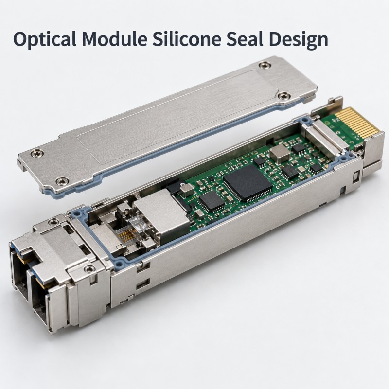
A silicone seal for an optical module housing or interface should be designed around the actual environmental ingress path rather than added as a generic rubber barrier.
Where an optical communication assembly requires moisture or dust protection, reliable sealing depends on a continuous sealing boundary, controlled silicone compression, stable housing dimensions, suitable silicone hardness, clean functional keep-out areas and repeatable assembly.
Depending on the structure, the sealing component may be a separate precision molded silicone gasket or an integrated silicone feature molded onto a suitable plastic or metal carrier.
The final design should be validated in the complete assembly under the environmental conditions defined by the customer.
Where Can Silicone Sealing Be Used Around an Optical Module Assembly?
Optical modules and surrounding communication assemblies combine optical, electrical and mechanical functions inside a compact structure.
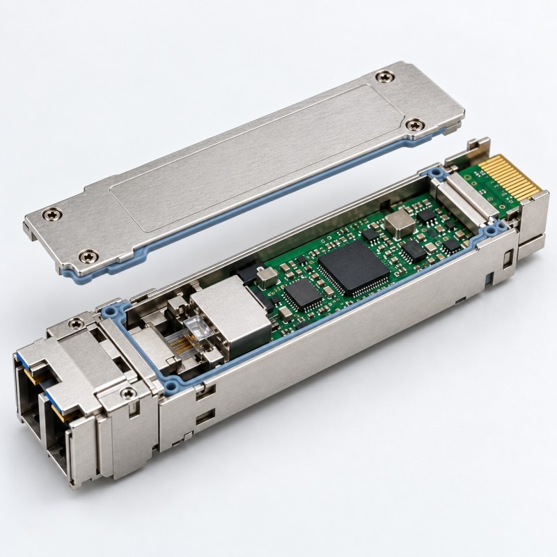
If the specific product requires environmental protection, silicone sealing may be evaluated around locations such as:
• Housing-to-cover interfaces
• Optical connector surrounding structures
• Cable or FPC transition areas
• Electrical interface surroundings
• Local plastic or metal carrier interfaces
• Small access openings requiring environmental isolation
• PCB or FPC protection areas inside a larger sealed assembly
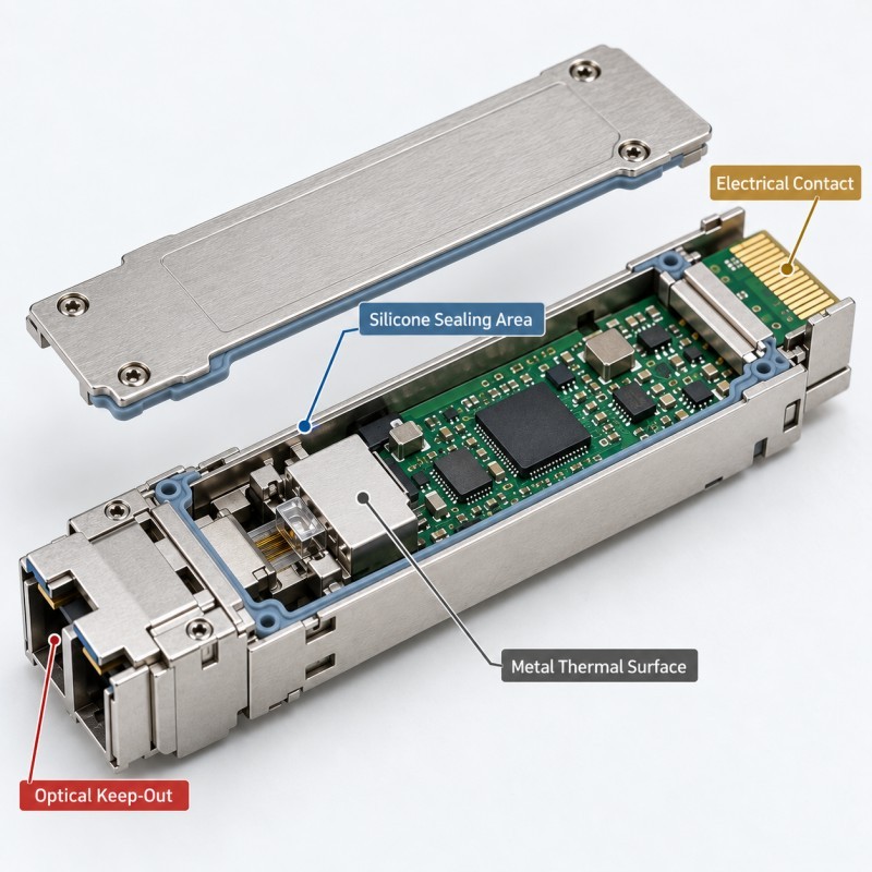
The silicone should only occupy the areas required for sealing or protection.
Optical paths, connector contacts, alignment features, heat-transfer surfaces, screw holes, test points and other functional areas must remain correctly exposed.
This boundary should be defined on the product drawing before tooling begins.
Why Is Optical Module Interface Sealing More Difficult Than It Looks?
A seal may look continuous in CAD while the real assembled product still contains a possible ingress path.
The sealing condition can be affected by:
• Housing dimensional tolerance
• Cover flatness
• Insert position
• Gasket thickness variation
• Uneven assembly force
• Connector geometry
• Local parting lines
• Small openings or gaps
• Silicone displacement during assembly
• Temperature-related dimensional changes
Compact optical assemblies can make this more difficult because sealing areas are often located close to electrical contacts, optical interfaces, fastening features and thermal-management structures.
The engineering question is therefore not simply “Where can silicone be added?”
The correct question is “Which continuous path must be blocked without interfering with another product function?”
1. Define the Complete Moisture and Dust Ingress Path First
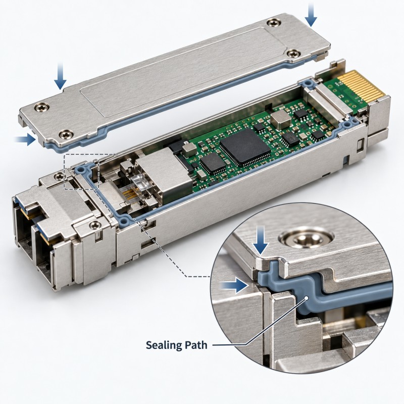
Before selecting gasket geometry, engineers should identify every path through which moisture, dust or other environmental contamination could reach the protected area.
Review the complete assembly rather than only the silicone drawing.
Possible paths may include:
• Housing-to-cover gaps
• Connector perimeter gaps
• Cable or FPC exits
• Plastic-to-metal interfaces
• Screw or locating openings
• Parting-line regions
• Adjacent assembly joints
Once these paths are identified, the sealing boundary can be designed as one continuous system.
If one section of the boundary is interrupted, increasing silicone thickness somewhere else will not necessarily solve the problem.
2. Silicone Compression Must Be Controlled
A silicone gasket normally needs controlled deformation to maintain contact with its mating surface.
If compression is too low, the assembly may develop:
• Incomplete sealing contact
• Local gaps
• Greater sensitivity to tolerance variation
• Inconsistent sealing between units
If compression is too high, the seal may:
• Distort excessively
• Roll or fold during assembly
• Require unnecessary assembly force
• Bulge into adjacent functional areas
• Experience increased long-term deformation
The objective is therefore not maximum compression.
The objective is a repeatable compression window that remains acceptable across the real dimensional tolerance of the housing and mating components.
3. Keep-Out Zones Are Critical Around Optical and Electrical Functions
An optical communication component may contain several areas where silicone must never enter.
Typical keep-out zones can include:
• Optical windows or paths
• Fiber alignment structures
• Electrical contacts
• Connector mating surfaces
• Test pads
• Screw holes
• Locating holes
• Threads
• Heat-transfer surfaces
• Assembly datums
These areas should be clearly identified before mold design.
For LSR overmolding, this requirement is particularly important because liquid silicone can enter very small uncontrolled gaps.
Mold shut-off surfaces and insert positioning must therefore isolate the silicone area from every functional opening that needs to remain clean and dimensionally stable.
4. Housing Tolerance Can Change the Real Sealing Condition
The nominal CAD model represents only one dimensional condition.
In production, the actual sealing interface may change because of:
• Plastic housing tolerance
• Metal housing dimensions
• Cover flatness
• Gasket height variation
• Insert position
• Fastener location
• Assembly gap
• Local warpage
A seal that works at the nominal dimension may become under-compressed at one tolerance extreme and over-compressed at another.
DFM should therefore evaluate minimum, nominal and maximum assembly conditions.
Critical dimensions should also be linked to a realistic inspection method, especially when measuring flexible silicone features.
5. Silicone Hardness Should Match Geometry and Assembly
Silicone hardness affects how a seal deforms when the optical module housing or interface is assembled.
A softer silicone may conform more easily to surface variation and require lower assembly force.
However, excessive softness may also increase movement, rolling or dimensional instability in certain structures.
A firmer silicone may maintain its molded shape more effectively, but it can require greater force to reach the required sealing contact.
Hardness should therefore be selected together with:
• Gasket cross-section
• Seal thickness
• Compression space
• Housing rigidity
• Mating geometry
• Assembly force
• Required environmental conditions
There is no single Shore hardness that is correct for every optical module sealing structure.
6. Separate Silicone Gasket or Integrated LSR Overmolding?
Both approaches can be considered, depending on the optical module or surrounding assembly structure.
A separate precision silicone gasket may be appropriate when:
• A stable groove or sealing seat already exists
• The seal must remain replaceable
• Independent gasket inspection is required
• Assembly can reliably control gasket positioning
An integrated LSR overmolded seal may be evaluated when:
• A sealing feature needs to remain fixed to a plastic or metal carrier
• Manual gasket placement creates assembly risk
• Several local sealing or protection features can be integrated
• The product already uses an insert suitable for precision overmolding
The correct choice depends on the substrate, geometry, functional areas, service requirements, tooling feasibility and validation plan.
Integrated overmolding should not be selected simply because it reduces part count. The insert and mold must also support repeatable manufacturing.
| Design Item | Engineering Purpose | Main Risk | Review Point |
Sealing path | Blocks environmental ingress | Interrupted seal | Complete assembly |
Compression | Maintains interface contact | Too low or too high | Tolerance stack |
Keep-out zone | Protects functional areas | Silicone contamination | Mold shut-off |
| Hardness | Controls deformation | Rolling or high force | Geometry + assembly |
| Housing tolerance | Controls real seal condition | Uneven compression | Worst-case dimensions |
| Insert positioning | Controls overmold location | Flash or misalignment | Fixture and datum |
7. Insert Positioning and Mold Shut-Off Control LSR Coverage
For an LSR overmolded optical or electronic interface component, the rigid insert must remain in a stable position during mold closing, injection, curing and demolding.
If the insert shifts, possible results include:
• Uneven silicone thickness
• Misaligned sealing features
• Silicone entering a keep-out zone
• Exposed substrate
• Excessive flash
• Incorrect final dimensions
The mold must also shut off accurately around the boundary between the silicone-covered area and the exposed functional area.
This becomes especially important around connectors, holes, metal surfaces, FPC terminals and precision mating features.
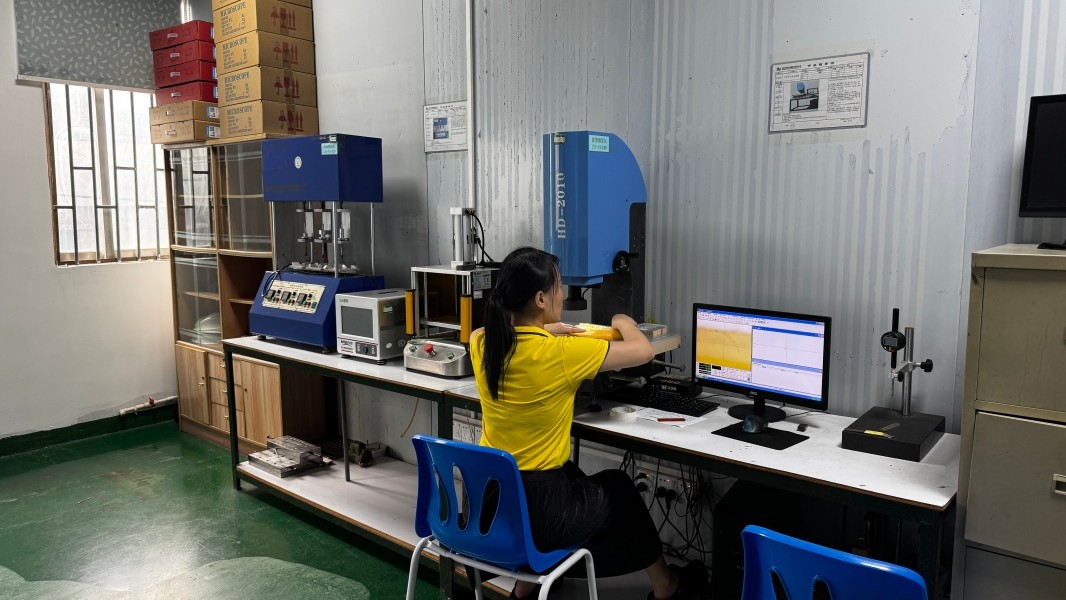
8. Moisture and Dust Protection Should Be Validated on the Final Assembly
The appearance of a molded silicone seal does not prove that the final optical communication assembly meets its environmental requirement.
Validation should be based on the customer's actual product specification.
Depending on the project, the validation plan may include:
• Dimensional inspection
• Visual inspection of the sealing path
• Assembly fit check
• Compression verification
• Air-leak or pressure-decay testing when applicable
• Dust exposure testing when specified
• Humidity or moisture exposure when specified
• Thermal cycling when required
• Functional testing after environmental exposure
• Pilot-production verification
Not every optical module requires the same test method or protection rating.
For this reason, the required environmental condition and acceptance criteria should be defined before tooling rather than assumed from another product.
What Should Be Included in an Optical Module Silicone Seal RFQ?
For a more accurate DFM review and quotation, provide as much of the following information as possible:
• 2D drawing
• 3D CAD model
• Complete assembly structure
• Housing and cover material
• Required sealing location
• Areas that must remain silicone-free
• Optical and electrical keep-out zones
• Gasket or seal geometry
• Silicone hardness requirement if defined
• Operating temperature
• Moisture or dust protection requirement
• Required validation method
• Assembly method
• Critical tolerance information
• Estimated order quantity
• Physical samples when available
For an LSR overmolded design, also identify the plastic, metal, FPC or other substrate material and clearly mark the required silicone coverage boundary.
This information allows the sealing structure and manufacturing feasibility to be reviewed before tooling starts.
How SiliconePlus Supports Precision Silicone Sealing Projects
SiliconePlus supports custom precision silicone molding and LSR overmolding for electronic components that require defined sealing, insulation, protection or rigid-soft integration.
Engineering and manufacturing support can include:
• Drawing and DFM review
• Precision silicone gasket development
• LSR injection molding
• Silicone over plastic
• Silicone over metal
• Insert positioning review
• Mold shut-off design
• Silicone coverage and keep-out review
• Dimensional inspection
• Sample development
• Pilot production
• OEM/ODM mass production
For optical communication projects, SiliconePlus should evaluate the actual customer's drawing and application requirements before confirming the silicone structure, material and validation method.
The goal is to manufacture the required sealing component—not to apply silicone to areas where it provides no functional benefit.
FAQ
Do All Optical Modules Need a Silicone Environmental Seal?
No. The sealing requirement depends on the actual module, enclosure, application environment and system architecture. Silicone sealing should be evaluated only where the product requires moisture, dust or other environmental protection.
Where Can Silicone Be Placed Around an Optical Module?
Depending on the structure, silicone may be used around selected housing interfaces, connector surroundings, cable or FPC transitions and other defined environmental sealing areas. Optical paths, contacts, heat-transfer surfaces and other functional areas should remain exposed where required.
Is a Separate Silicone Gasket Better Than LSR Overmolding?
Neither method is universally better. A separate gasket can be appropriate for a controlled groove, while LSR overmolding may be useful when the sealing feature should remain integrated with a plastic, metal or FPC carrier. The decision depends on the complete assembly.
Can LSR Overmolding Cover Optical or Electrical Contacts?
Those areas should normally remain silicone-free when they are required for optical transmission, electrical connection, testing or assembly. Functional keep-out areas should be defined before tooling so that mold shut-off and insert positioning can control silicone coverage.
Does an Optical Module Silicone Seal Automatically Provide IP67 or IP68 Protection?
No. A silicone component alone does not establish an IP rating. Any required environmental performance must be validated on the final assembly according to the customer's defined test conditions and acceptance criteria.
What Information Is Needed to Quote an Optical Module Silicone Seal?
Provide the 2D/3D drawing, assembly structure, substrate material, required sealing area, silicone-free zones, operating conditions, material requirements, validation requirements and estimated order quantity.
Conclusion
Silicone sealing for optical module housings and interfaces should be designed around the complete product structure rather than treated as a separate rubber-part decision.
Reliable environmental protection depends on the combined control of:
• Ingress path
• Continuous sealing boundary
• Silicone compression
• Housing tolerance
• Silicone hardness
• Keep-out zones
• Insert positioning
• Mold shut-off
• Assembly conditions
• Final validation
For compact optical communication assemblies, the most important design principle is selective sealing: silicone should protect the required interface while leaving optical, electrical, thermal and mechanical functional areas correctly exposed.
A DFM review before tooling can identify these boundaries and manufacturing risks earlier, when changes are still easier to make.
Developing a Custom Silicone Seal for an Optical Communication Component?
If your optical module, transceiver interface or related communication assembly requires a custom silicone gasket or integrated LSR sealing structure, send your 2D/3D drawing, substrate material, required silicone coverage, functional keep-out areas, operating conditions and estimated quantity to the SiliconePlus engineering team.
Our team can review the sealing path, compression structure, insert positioning, mold shut-off, tolerance risks and manufacturing feasibility before tooling and sampling.
For environmental performance requirements, final acceptance conditions should be defined according to the actual assembled product and customer specification.