How Should Silicone Seals Be Designed for Liquid Cooling Connectors and Manifold Interfaces?
- Share
- publisher
- SiliconePlus Engineering Team
- Issue Time
- Sep 18,2026
Summary
Liquid cooling connector seals must control coolant leakage across real pressure, tolerance, temperature and fluid-exposure conditions. This guide explains sealing paths, axial and radial compression, plastic and metal carrier design, coolant compatibility, LSR overmolding, tolerance stack-up and leak-test validation for liquid cooling connector and manifold interfaces.
Answer Excerpt
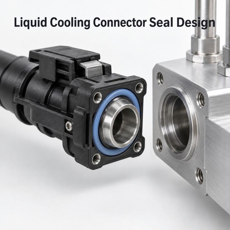
A silicone seal for a liquid cooling connector or manifold interface should be designed around the actual coolant leakage path, pressure condition, assembly direction and dimensional tolerance of the complete system.
Reliable sealing depends on more than placing a soft silicone ring around the connector. Engineers need to control sealing geometry, compression, rigid support, mating-surface dimensions, coolant exposure, thermal cycling and the final leak-test condition.
Depending on the product structure, the silicone may be manufactured as a separate precision molded seal or integrated directly onto a suitable plastic or metal carrier through LSR overmolding.
Because liquid cooling systems can use different coolant chemistries and operating conditions, material compatibility should be validated with the actual fluid rather than assumed from generic silicone properties.
Where Are Silicone Seals Used in Liquid Cooling Connector Assemblies?
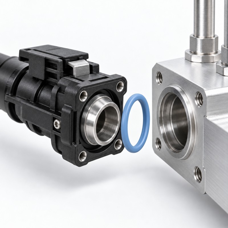
Liquid cooling systems contain multiple interfaces where coolant must move from one component to another without creating an uncontrolled leakage path.
Depending on the system architecture, a silicone sealing component may be evaluated around:
• Connector-to-manifold interfaces
• Tube or fitting connection areas
• Plastic connector carriers
• Metal connector carriers
• Manifold ports
• Local housing-to-connector interfaces
• Sensor or electrical feedthrough surroundings
• Cable exit areas requiring environmental isolation
• Other defined fluid-interface boundaries
Not every sealing location performs the same function.
Some seals separate the internal coolant circuit from the outside environment, while others protect an adjacent electrical or cable interface from moisture.
These functions should be identified separately before the silicone geometry is designed.
Why Can a Liquid Cooling Connector Leak Even When the Seal Looks Correct?
A connector seal can appear continuous after assembly and still contain a microscopic leakage path.
Possible causes include:
• Insufficient local compression
• Excessive compression and seal distortion
• Connector-body warpage
• Incorrect groove dimensions
• Uneven mating surfaces
• Insert-position variation
• Plastic or metal carrier tolerance
• Parting-line or flash interference
• Seal rolling during assembly
• Bonding-edge separation
• Long-term compression loss
• Thermal expansion differences
• Coolant-related material changes
This is why visual inspection alone cannot confirm liquid-tight performance.
The complete connector, seal, mating component and coolant circuit should be treated as one sealing system.
1. Define the Coolant Leakage Path Before Designing the Seal
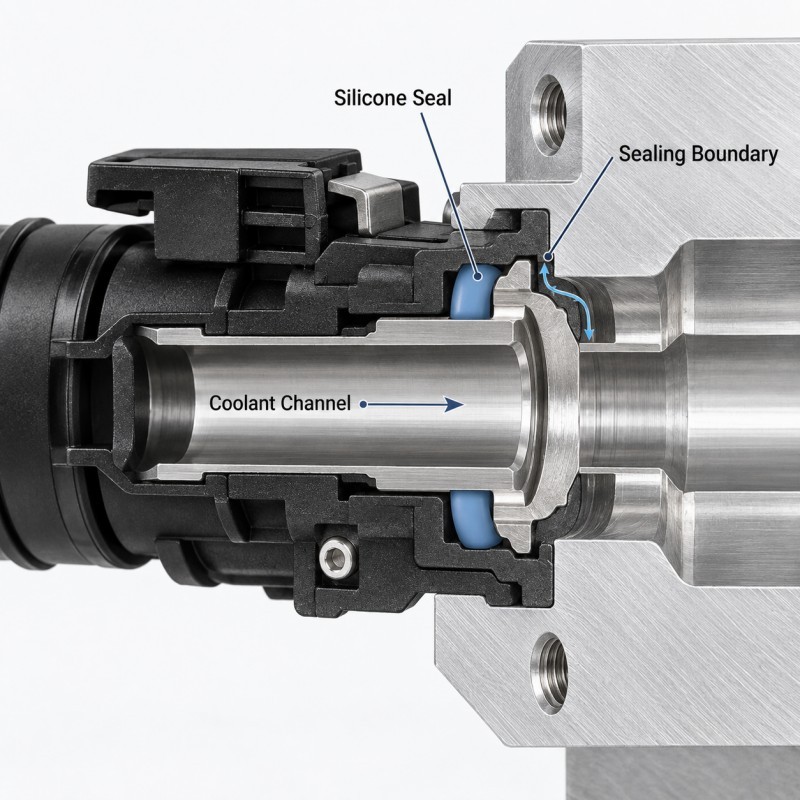
The first engineering step is to determine exactly where coolant is located and which boundary prevents it from escaping.
Engineers should review:
• Internal coolant port
• Connector bore
• Manifold interface
• Mating shoulder
• Plastic-to-metal boundary
• Tube or fitting interface
• Assembly gap
• Fastener or locking location
• Adjacent electrical structures
The seal should interrupt every continuous path between the pressurized coolant region and the external environment.
Adding more silicone to one location does not compensate for an unsealed path somewhere else.
For an overmolded component, engineers should also check whether coolant could migrate along the interface between silicone and the rigid carrier.
2. Axial and Radial Seals Require Different Compression Control
Liquid cooling connector interfaces can create different sealing directions.
An axial seal is compressed mainly along the connector or cover closing direction.
A radial seal is compressed mainly between inner and outer cylindrical or near-cylindrical mating surfaces.
The correct silicone profile depends on the actual assembly motion.
For axial sealing, engineers should review:
• Final assembly gap
• Stop height
• Seal height
• Contact width
• Mating-surface flatness
• Fastener or locking force
For radial sealing, engineers should review:
• Mating diameter
• Seal outside or inside diameter
• Insertion direction
• Lead-in geometry
• Surface finish
• Seal support
• Risk of rolling or cutting
The seal geometry should follow the real compression direction instead of using the same profile for every connector.
3. Compression Must Be Controlled by the Rigid Structure
A reliable connector design should not depend on an operator simply tightening the assembly until it “feels sealed.”
Where practical, a rigid structural feature should define the final mating position.
Possible assembly-control features include:
• Connector shoulders
• Plastic bosses
• Metal stops
• Mating flanges
• Housing steps
• Controlled snap-fit positions
• Screw-column contact surfaces
The rigid structure reaches its intended stop while the silicone remains within the required working compression range.
If the stop closes too early, the seal may remain under-compressed.
If the geometry allows excessive closing travel, the silicone may flatten, roll, bulge or experience unnecessary long-term deformation.
4. Coolant Compatibility Cannot Be Assumed From the Word “Silicone”
Liquid cooling systems do not all use the same fluid.
Depending on the system, the sealing material may be exposed to different:
• Coolant chemistries
• Water-to-glycol ratios
• Corrosion inhibitors
• Additives
• Cleaning agents
• Operating temperatures
• Pressure conditions
• Exposure durations
The term “silicone rubber” alone does not prove compatibility with every coolant formulation.
Fluid exposure can potentially affect:
• Volume or swelling behavior
• Hardness
• Tensile properties
• Surface condition
• Compression recovery
• Bonding interface
• Long-term sealing performance
Before approving a material, the project should define the actual coolant formulation, concentration, operating temperature and required exposure period.
Where validated compatibility data are not available for the exact fluid and silicone grade, testing should be performed before long-term production approval.
5. Plastic and Metal Carriers Must Remain Dimensionally Stable
An integrated silicone seal cannot perform consistently if the rigid structure supporting it changes shape.
For a plastic connector carrier, engineers should evaluate:
• Plastic grade
• Wall thickness
• Molded-in stress
• Flatness
• LSR molding temperature exposure
• Silicone injection pressure
• Assembly load
• Operating temperature
For a metal carrier, review:
• Metal material
• Machining tolerance
• Surface finish
• Coating or plating
• Edge geometry
• Flatness
• Cleanliness
• Thermal expansion
If the carrier bows, tilts or becomes off-center, one side of the silicone seal may become over-compressed while another side loses contact pressure.
6. Separate Seal or LSR Overmolded Connector?
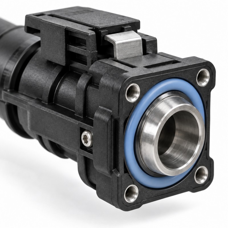
A separate silicone seal and an integrated LSR overmolded seal can both be appropriate, depending on the connector architecture.
A separate molded seal may be suitable when:
• A controlled seal groove already exists
• The seal needs to be replaceable
• Standardized assembly is preferred
• Independent seal inspection is required
However, assembly control must prevent:
• Missing seals
• Twisting
• Stretching
• Incorrect orientation
• Pinching
• Contamination
An LSR overmolded connector seal may be evaluated when:
• The silicone should remain permanently positioned on the carrier
• A local sealing feature can be integrated directly with the rigid insert
• Manual seal installation creates assembly variation
• Several sealing or protective features can be combined
• The carrier geometry is suitable for insert molding
Overmolding does not automatically create a leak-free interface.
The silicone-to-carrier boundary, retention structure, mold shut-off, insert position and final assembly compression still need to be engineered.
Design Item | Why It Matters | Main Risk | What to Review |
Leakage path | Defines sealing boundary | Hidden coolant path | Complete connector assembly |
Seal direction | Controls deformation | Wrong seal profile | Axial or radial motion |
| Compression | Creates contact pressure | Under/over-compression | Min/nominal/max condition |
Coolant exposure | Affects material | Swelling or property change | Actual fluid |
| Carrier stability | Supports seal | Warpage and uneven contact | Plastic/metal dimensions |
| Retention | Keeps silicone integrated | Edge lifting | Bonding + mechanical lock |
| Leak testing | Confirms final performance | False confidence from appearance | Pressure and acceptance criteria |
7. Mechanical Retention Can Improve Overmolded Seal Stability
When silicone is overmolded onto a connector carrier, chemical adhesion is only one possible method of keeping the two materials integrated.
Depending on the structure, mechanical retention can also be used.
Possible features include:
• Through-holes
• Retaining slots
• Undercuts
• Wraparound edges
• Locking grooves
• Windows
• Anchoring ribs
These features allow cured silicone to lock physically into the rigid substrate.
Mechanical retention can be especially useful where the overmolded seal experiences compression, thermal cycling, assembly stress or local peel loading.
However, the retention feature must not create a secondary coolant leakage path or a trapped-air region.
8. Thermal Cycling Can Change Connector Seal Compression
A liquid cooling connector may repeatedly experience temperature changes during startup, high-load operation, shutdown and environmental testing.
Silicone, engineering plastic and metal do not necessarily expand and contract by the same amount.
Repeated temperature changes may contribute to:
• Connector-body dimensional change
• Seal-compression variation
• Bonding-edge stress
• Local delamination
• Carrier warpage
• Reduced sealing contact pressure
• Leakage that appears only after cycling
A connector that passes the initial leak test should therefore be retested after the required thermal exposure when the application demands it.
The exact temperature range and number of cycles should come from the customer's project requirement rather than from a generic universal value.
9. Long-Term Compression Recovery Matters After Initial Testing
A silicone connector seal may remain compressed throughout the service life of the liquid cooling system.
Initial contact pressure can be sufficient while the seal is new, but long-term performance may change after:
• Continuous compression
• Elevated temperature
• Thermal cycling
• Coolant exposure
• Pressure variation
• Material aging
• Carrier deformation
For this reason, initial leak performance and long-term sealing reliability should be treated as different validation stages.
A seal that passes the first pressure test should not automatically be assumed to maintain identical recovery after extended service conditions.
10. Electrical and Cable Interfaces Need a Different Sealing Boundary
Some liquid cooling assemblies place electrical sensors, cables, monitoring components or control interfaces close to coolant connectors.
These interfaces may need protection from external moisture or from coolant leakage, but their sealing function is different from the primary fluid seal.
Engineers should clearly separate:
• Primary coolant containment seal
• Connector-to-housing seal
• Electrical interface protection
• Strain relief
• Environmental dust and moisture barrier
Trying to make one undefined mass of silicone perform all of these functions can make both tooling and validation more difficult.
Each sealing boundary should have a clear purpose and acceptance condition.
How Should a Liquid Cooling Connector Seal Be Validated?
Validation should be performed on the complete mating assembly rather than on the loose silicone component alone.
A project-specific validation plan may include:
1. Dimensional Inspection
Confirm seal height, width, position, carrier dimensions and critical mating features.
2. Assembly Check
Confirm that the connector reaches its intended final position without seal rolling, cutting, pinching or excessive force.
3. Minimum and Maximum Compression Review
Evaluate realistic tolerance extremes rather than only the nominal CAD condition.
4. Pressure or Leak Testing
Define the test medium, test pressure, stabilization time, test duration, temperature and allowable leakage rate.
5. Coolant Exposure
Where the silicone directly contacts coolant, evaluate the approved material using the actual fluid or a defined representative medium.
6. Thermal Cycling
Repeat leakage testing after the required temperature cycling when applicable.
7. Aging or Long-Term Compression
Evaluate sealing recovery after the required exposure conditions.
8. Pilot Production
Test multiple consecutive parts and, where relevant, multiple cavities before mass-production approval.**
The objective is repeatable liquid-tight performance across production—not one sample that happens to pass.
Do Not Replace a Coolant Leak Specification With an IP Rating
IP67 and IP68 are useful specifications for defined enclosure water-ingress conditions, but an internal liquid cooling circuit is not the same test environment.
A coolant connector may have its own:
• Internal pressure
• Coolant chemistry
• Operating temperature
• Pressure cycle
• Test duration
• Allowable leakage rate
• Life requirement
Therefore, a connector should be validated against the actual liquid cooling leakage specification instead of assuming that an IP rating proves coolant-circuit performance.
What Should Be Included in a Liquid Cooling Connector Seal RFQ?
For a more accurate engineering review and quotation, provide as much of the following information as possible:
• 2D drawing
• 3D CAD model
• Complete connector and manifold assembly
• Plastic or metal carrier material
• Coolant-side sealing location
• Silicone coverage area
• Areas that must remain silicone-free
• Axial or radial assembly direction
• Minimum and maximum mating dimensions
• Coolant type and concentration
• Operating temperature
• Operating pressure
• Leakage acceptance requirement
• Thermal-cycle requirement
• Silicone hardness requirement if defined
• Expected order quantity
• Physical insert or mating samples when available
If the silicone will directly contact coolant, the exact fluid information should be provided before material compatibility is confirmed.
For an overmolded connector, the drawing should clearly distinguish the rigid carrier, silicone area and functional surfaces that must remain exposed.
How SiliconePlus Supports Liquid Cooling Connector Sealing Projects
SiliconePlus supports custom precision silicone molding and LSR overmolding for applications that require controlled sealing and rigid-soft integration.
For liquid cooling connector projects, engineering and manufacturing support can include:
• Drawing and DFM review
• Precision silicone seal development
• LSR injection molding
• Silicone over plastic
• Silicone over metal
• Connector carrier review
• Seal geometry review
• Insert positioning
• Mold shut-off design
• Mechanical retention design
• Flash-control review
• Dimensional inspection
• Sampling and pilot production
• OEM/ODM mass production support
Material compatibility, pressure capability and leakage performance should be confirmed according to the customer's actual coolant, assembly structure and validation specification.
SiliconePlus should not treat every liquid cooling connector as the same product—the seal must be developed around the real carrier, mating interface and coolant conditions.
FAQ
Can Silicone Be Used for Every Liquid Cooling Connector Seal?
No material should be assumed suitable for every liquid cooling system. The silicone grade must be evaluated according to the actual coolant chemistry, concentration, temperature, pressure, exposure time and sealing structure.
What Is the Difference Between an Axial and Radial Connector Seal?
An axial seal is mainly compressed along the connector closing direction, while a radial seal is compressed between mating inner and outer surfaces. Each requires different seal geometry, support and assembly control.
Is an LSR Overmolded Connector Better Than a Separate Silicone Seal?
Not automatically. Overmolding can integrate the sealing feature with a plastic or metal carrier and reduce separate assembly, while a removable molded seal may be preferable in other structures. The decision depends on the actual product architecture.
Can Coolant Compatibility Be Confirmed Only From Silicone Hardness?
No. Shore hardness does not determine coolant compatibility. The exact silicone formulation and actual coolant must be evaluated under the required temperature and exposure conditions.
Does IP68 Mean a Liquid Cooling Connector Will Not Leak Coolant?
No. An IP rating and an internal coolant leakage specification are different test conditions. The connector should be validated using the required pressure, fluid, temperature, duration and allowable leakage criteria for the liquid cooling system.
What Information Is Needed for a Custom Liquid Cooling Connector Seal Quote?
Provide the 2D/3D drawing, connector and manifold structure, carrier material, coolant type, operating pressure and temperature, seal location, mating dimensions, leakage requirement and estimated order quantity.
Conclusion
A reliable liquid cooling connector seal is the result of a controlled sealing system—not simply a soft silicone material around a fitting.
The design should coordinate:
• Coolant leakage path
• Axial or radial sealing direction
• Compression range
• Rigid assembly stop
• Silicone geometry
• Coolant compatibility
• Plastic or metal carrier stability
• Mechanical retention
• Thermal cycling
• Long-term compression recovery
• Pressure and leakage validation
For integrated structures, LSR overmolding can be evaluated when the silicone sealing feature needs to remain accurately positioned on a plastic or metal carrier.
However, the final solution should always be based on the actual coolant, connector geometry, mating structure and test requirements.
The earlier these conditions are defined, the easier it is to identify sealing risks before tooling and pilot production.
Developing a Liquid Cooling Connector or Manifold Seal?
If you are developing a liquid cooling connector, manifold interface, plastic carrier, metal carrier or related sealing component, send your 2D/3D drawing, substrate material, coolant information, operating pressure, temperature, leakage requirement and estimated quantity to the SiliconePlus engineering team.
Our team can review the sealing path, compression direction, insert structure, mold shut-off, tolerance risks and whether a separate precision silicone seal or integrated LSR overmolding solution is more appropriate for your project.
For coolant-contact applications, final material compatibility and sealing performance should be confirmed according to the actual fluid and agreed validation conditions.