How Should Silicone Grip Texture and Coverage Be Designed on an LSR-Overmolded Industrial Control Knob?
- Share
- publisher
- SiliconePlus Engineering Team
- Issue Time
- Oct 26,2026
Summary
An LSR-overmolded industrial control knob combines a rigid plastic core with a custom silicone grip surface. This guide explains how to define grip texture, silicone coverage, shaft-interface clearance, mold parting lines and inspection criteria before tooling. Final grip, fit and durability requirements should be validated on representative parts.
Answer Excerpt
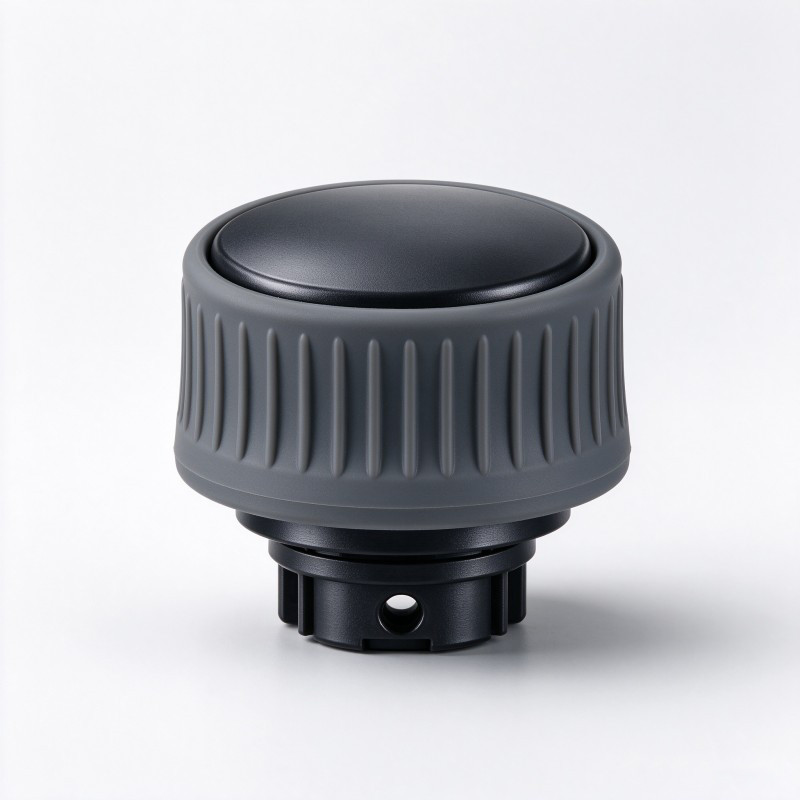
An LSR-overmolded industrial control knob combines a rigid plastic core with a molded silicone grip surface. The design must coordinate the grip texture, silicone coverage boundary, mounting interface and mold layout as one component. Texture that looks attractive in a rendering may be difficult to mold, inspect or clean if its geometry is not reviewed early. The silicone layer must also remain clear of functional interfaces such as the shaft bore or mounting features. Before tooling, buyers should define the intended grip areas, appearance requirements, fit conditions and acceptance criteria. Grip, wear and operating performance should be validated using representative parts in the intended application.
What Does the Silicone Grip Need to Do?
An industrial control knob is a functional interface between an operator and a machine or instrument. Its silicone surface may be intended to improve tactile feel, provide a more compliant contact surface or distinguish a gripping zone from the rigid core. The correct design depends on the intended operating environment and the way the knob is used.
Before selecting a texture, define the primary requirements:
- Which areas are intended for finger contact?
- Will the knob be rotated with fingertips, a thumb or a full-hand grip?
- Does the design need a smooth top face and a textured sidewall, or another combination?
- Which surfaces must remain exposed plastic or remain free of silicone?
- Does the knob need to fit a particular shaft, mounting bore or mating component?
- Will operators use gloves, and are cleaning agents or environmental contaminants relevant?
- Which appearance, dimensional and functional criteria will be used for sample approval?
These questions help distinguish cosmetic preferences from functional requirements. For example, a ribbed sidewall may be selected for tactile differentiation, but its actual effect on handling should be evaluated in the intended application rather than assumed from the visual design.
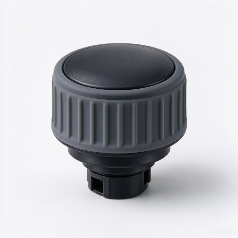
SiliconePlus offers a custom LSR-overmolded industrial control knob with a rigid plastic core and customizable silicone grip surface. The final substrate, texture and mounting interface should be confirmed against the customer's drawings and application requirements.
How Should Silicone Grip Texture Be Selected?
Grip texture should be selected according to the required tactile feel, the available surface area, the knob geometry and the manufacturing method. The design should be easy to communicate in a drawing and possible to inspect consistently.
Common design directions include:
Smooth silicone surfaces. A smooth surface can suit a minimalist appearance or an interface that needs simple cleaning. Its suitability depends on the actual application and user requirements.
Raised ribs or grooves. Repeated features can create a more defined tactile pattern. Their spacing, height, depth and orientation should be reviewed against the available grip area and the intended rotation direction.
Localized texture. A textured region can distinguish the primary gripping zone from a smooth top face or other visual features. The boundary between textured and smooth areas should be clear in the product definition.
Custom patterns. A logo, directional feature or application-specific pattern may be possible, but its geometry must be reviewed for tooling feasibility, appearance consistency and inspection.
Texture should not be selected from a visual rendering alone. Very fine details, deep grooves, narrow valleys or abrupt transitions may create tooling and demolding considerations. The appropriate geometry depends on the part design and the mold concept.
During design review, define the texture using a drawing, CAD model or approved physical reference. Where a visual sample is used, make sure the required texture and appearance can be evaluated consistently across future production samples.
Grip Texture Design Review
| Design feature | What to define | What to review |
Grip-zone location | Which areas receive silicone texture | Whether the intended contact area is clearly defined |
Texture type | Smooth, ribs, grooves or custom pattern | Fit with the intended handling method |
Feature geometry | Dimensions and profile shown in the drawing or CAD model | Tooling feasibility and repeatability |
Texture transition | Where the textured area begins and ends | Appearance consistency and clear boundaries |
| Top-face design | Smooth, textured or partially covered | Visual requirements and access to any functional features |
| Cleaning requirements | Relevant cleaning method and environment | Whether the texture can be maintained as intended |
| Acceptance criteria | Approved visual or dimensional reference | How samples and production parts will be evaluated |
How Should Silicone Coverage Be Defined Around the Plastic Core?
The silicone coverage boundary should be defined against the complete knob assembly, including the plastic core and mounting interface. It should not be left to interpretation during mold design.
A coverage review should identify:
- The areas that must receive silicone
- The plastic surfaces that must remain exposed
- The boundary between the silicone grip and the rigid core
- The top-face and sidewall geometry
- The shaft bore, mounting features or other functional interfaces
- Any cosmetic edge that must remain consistent
- The intended relationship between the molded knob and its mating assembly
The shaft interface deserves particular attention. Silicone that extends into an area intended for a rigid mounting connection may affect fit or assembly. The final interface geometry must be defined from the customer's drawing rather than assumed from a generic knob design.
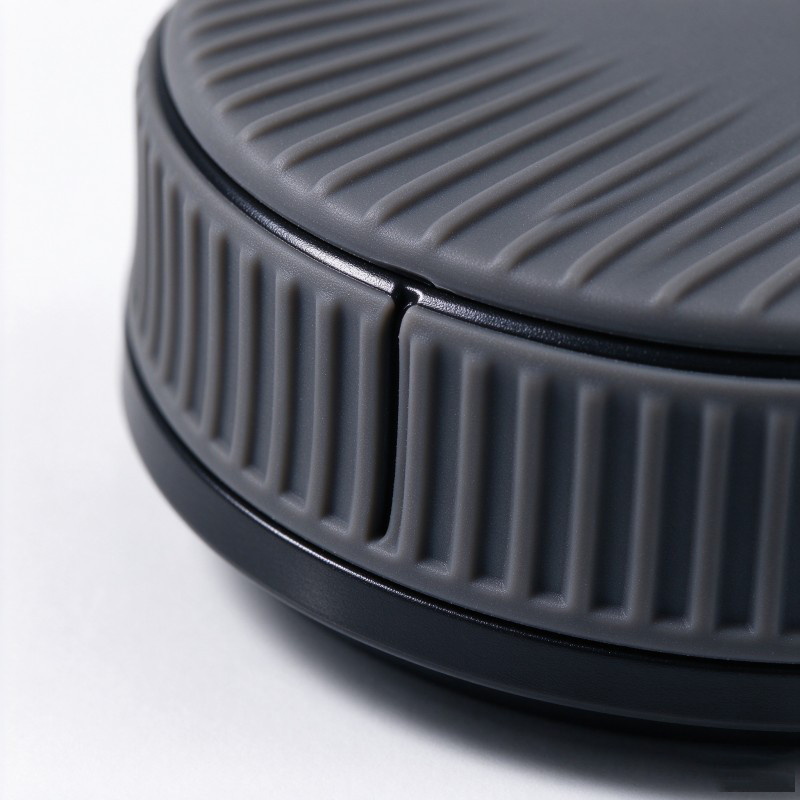
The coverage boundary should also be reviewed in three dimensions. A top view alone may not reveal conflicts between a textured grip, a curved sidewall, a mounting bore and the mold parting line.
For custom projects, silicone mold design capabilities can be reviewed during the DFM stage to assess the proposed geometry, parting-line position, demolding direction and surface requirements. The final mold arrangement must be determined for the actual component design.
The approved drawing or CAD model should make the silicone-covered and exposed areas unambiguous before tooling approval.
What Should Be Checked at the Shaft and Mounting Interface?
A control knob can have a well-designed silicone grip and still be unsuitable for assembly if its mounting interface is not defined correctly.
The mounting interface may include a shaft bore, a keyed profile, a flat, a threaded feature or another geometry specified by the customer. The actual design depends on the equipment and the mating component; no single interface should be assumed for all knobs.
Before tooling, confirm the following:
- The mounting-interface drawing and relevant dimensions
- The relationship between the rigid plastic core and the shaft
- Which surfaces must remain free of silicone
- The required orientation of the knob relative to the shaft
- Any clearance or interference requirements for assembly
- Whether the top face or sidewall has a defined orientation
- The inspection method for the critical mounting dimensions
The silicone coverage should not obstruct a required bore or change the intended mating geometry. The tooling concept must locate the plastic insert consistently while preserving the required functional surfaces.
After molding, evaluate the mounting interface against the approved drawing and perform a representative assembly check. If the knob is intended to operate a specific device, verify the assembled interface in that application.
Do not claim a particular operating torque, rotational life or retention force unless the project has defined and validated those requirements.
Interface Risks and Inspection Focus
| Interface area | Potential concern | Recommended review |
Shaft bore | Silicone intrusion or dimensional mismatch | Check bore condition and approved dimensions |
Keyed or flat feature | Incorrect orientation or fit | Verify geometry and assembly orientation |
Silicone-to-plastic boundary | Uneven coverage or unwanted edge variation | Compare the molded boundary with the approved reference |
Top face | Unintended coverage or appearance variation | Inspect coverage and cosmetic requirements |
| Grip ribs or grooves | Incomplete detail or inconsistent appearance | Check texture against the approved sample or drawing |
| Parting-line area | Visible flash or mismatch | Inspect the agreed cosmetic and functional zones |
| Final assembly | Interference or poor fit | Conduct a representative assembly check |
How Can the Mold Design Support Consistent Texture and Coverage?
The mold design must reproduce the intended grip texture and coverage boundary while locating the plastic core consistently. These requirements should be reviewed together rather than handled as separate cosmetic and structural tasks.
The DFM review should cover:
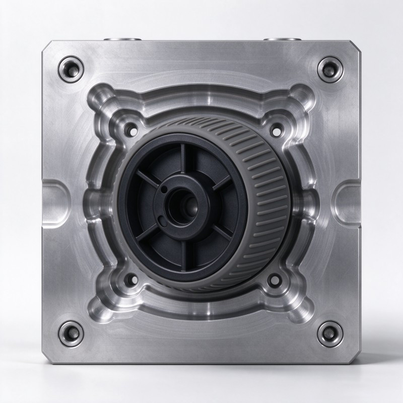
Insert positioning. Identify stable locating features on the plastic core and confirm that the insert can be loaded consistently.
Texture transfer. Review whether the intended rib, groove or custom pattern can be represented in the mold geometry and inspected on the molded surface.
Parting-line placement. Consider where the mold parting line will appear relative to the main grip area and any visible surface.
Coverage shut-off. Define the boundaries where silicone must stop and where plastic or mounting features must remain exposed.
Demolding. Review the selected texture and surrounding geometry for demolding feasibility. Undercuts and deep features may require a project-specific mold strategy.
Appearance acceptance. Establish an approved reference for color, texture, surface finish and visible boundaries before production approval.
A rendered image is useful for communicating the intended appearance, but it does not prove that every detail can be molded or demolded as drawn. The final design should be reviewed with the tooling team and evaluated using representative samples.
SiliconePlus provides liquid silicone injection molding services for custom silicone components. Material selection, insert compatibility, mold design and process feasibility must be confirmed for each project rather than assumed from the general process name.
How Should the Finished Knob Be Inspected?
The inspection plan should reflect the approved drawing, appearance requirements and intended operating function. It should be established before sample approval so that the customer and manufacturer evaluate the same features.
Depending on the project, the plan may include:
- Visual inspection of silicone coverage and exposed plastic areas
- Comparison of the grip texture with an approved sample or drawing
- Inspection of the shaft bore and other mounting dimensions
- Review of the silicone-to-plastic boundary and parting-line area
- Confirmation that the molded knob fits the specified mating component
- Functional evaluation in the intended control assembly
- Additional wear, cleaning or environmental tests where the application requires them
Not every project requires the same tests. The customer should define the relevant use conditions and acceptance criteria before testing begins.
For example, if the knob will be handled with gloves or exposed to specific cleaning agents, those conditions should be included in the evaluation plan where they are important to product use. The result must be based on representative parts and actual test conditions, not on the appearance of a CAD model.
Once a sample is approved, keep the approved drawing, visual reference and inspection criteria aligned with the production specification. This helps reduce ambiguity when the design moves from prototype to repeat orders.
What Should Buyers Include in an RFQ?
For an accurate quotation and feasibility review, buyers should provide enough information to define the complete knob, its mounting interface and the intended grip surface.
A useful RFQ package includes:
- A 2D drawing and, where available, a 3D CAD model
- The specified plastic core material or material requirements
- The intended silicone coverage area
- Grip texture type, location and available design references
- Shaft bore or mounting-interface geometry
- Areas that must remain free of silicone
- Color and cosmetic appearance requirements
- The mating component or assembly drawing, where available
- Relevant operating, cleaning or environmental conditions
- Required inspection and functional acceptance criteria
- Prototype quantity, estimated production volume and target schedule
If the design has a preferred tactile feel but no defined texture geometry, provide a reference sample or explain the use case. The manufacturer can then review possible design directions, but the final texture should be agreed before tooling.
Also distinguish mandatory requirements from preferences. For example, a particular color may be a branding preference, while a shaft interface dimension may be essential for assembly.
A complete RFQ gives the engineering team a basis to assess substrate compatibility, mold feasibility, appearance requirements, inspection methods and sample approval before committing to the production design.
Frequently Asked Questions
Can silicone grip texture be customized on an LSR-overmolded control knob?
Yes. The texture, coverage area, color and overall shape can be specified for a custom design. The selected geometry should be reviewed for mold feasibility and confirmed on representative samples.
Should the entire control knob be covered with silicone?
Not necessarily. The coverage depends on the intended grip area, the rigid core, the mounting interface and appearance requirements. Areas that must remain exposed should be clearly identified in the drawing.
Can silicone cover the shaft bore?
Only if the design explicitly requires it and the interface is intended to accommodate that structure. If the bore is a functional mounting interface, the coverage boundary should be defined to preserve the required fit.
Does a ribbed silicone surface guarantee better grip?
No. The effect depends on the texture geometry, silicone material, user interaction and operating environment. Grip performance should be evaluated in the intended application rather than inferred from a rendering.
What should be checked before approving a control knob sample?
Review the silicone coverage, texture appearance, plastic-to-silicone boundary, mounting dimensions and fit with the mating component. Any required operating, wear or environmental tests should be defined and completed against agreed acceptance criteria.
Conclusion
A well-designed LSR-overmolded industrial control knob must coordinate its silicone grip surface with the rigid plastic core and the mounting interface.
The main tasks are to define the intended grip area, specify a manufacturable texture, establish the silicone coverage boundary, preserve functional mounting features and review the mold design before tooling. The finished component should then be inspected against an approved drawing and evaluated in the intended assembly.
A texture that looks good in a rendering is only a starting point. The final design should be validated against actual handling, fit and application requirements.
For OEM and ODM buyers, providing complete drawings, reference samples and acceptance criteria early helps the manufacturer assess feasibility and quote the right custom component.
Discuss Your Custom Control Knob
Developing an industrial control knob with a rigid plastic core and a custom silicone grip?
Send SiliconePlus your drawing or sample, plastic material details, grip texture preferences, mounting-interface dimensions and application requirements. Our team can review the proposed silicone coverage, tooling feasibility and sample-validation needs for your project.
To discuss your requirements, contact SiliconePlus for a project-specific review and quotation.