How Should Multi-Lip Silicone Seals Be Designed for LSR Overmolded Automotive Connectors?
- Share
- publisher
- SiliconePlus Engineering Team
- Issue Time
- Aug 17,2026
Summary
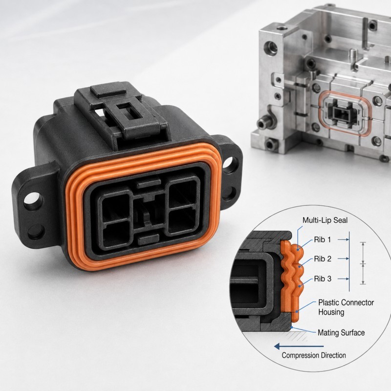
Multi-lip silicone seals use several controlled sealing ribs to create multiple contact bands between an LSR overmolded automotive connector and its mating housing. Reliable design depends on rib height, width, spacing, root radius, silicone hardness, compression direction, mating-surface tolerance and assembly stop. The complete seal should be validated under minimum, nominal and maximum compression conditions before mass production.
Answer Excerpt
Multi-lip silicone seals use several controlled sealing ribs to create multiple contact bands between an LSR overmolded automotive connector and its mating housing. Reliable performance depends on rib height, width, spacing, root radius, silicone hardness, compression direction, mating-surface tolerance and the final assembly stop. There is no universal rib geometry or compression value for every connector; the complete sealing system must be evaluated under the actual assembly and waterproof test conditions.
Automotive connector sealing is not achieved simply by adding more silicone around a plastic housing.
The silicone must contact the mating component in a predictable way while remaining flexible enough to accommodate dimensional variation, housing warpage, vibration and environmental changes.
A multi-lip structure divides the main sealing interface into several narrower contact bands instead of relying on one broad uncontrolled surface.
This can provide additional sealing paths, but only when every rib is positioned and compressed correctly.
If one rib is too high, too soft or poorly supported, it may roll or absorb too much of the assembly movement. If the ribs are too low or too stiff, some sealing bands may never develop sufficient contact.
For real EV connector and automotive electronics projects, a custom automotive connector silicone seal should therefore be reviewed together with its mating housing rather than as a stand-alone molded part.
Why Use Multiple Sealing Lips on an Automotive Connector?
Multiple sealing ribs can create several controlled contact locations between the silicone and mating housing.
This is useful because the mating plastic surface is never perfectly ideal in production.
Variation may come from:
• Housing flatness
• Connector molding tolerance
• Surface texture
• Assembly alignment
• Temperature change
• Vibration
• Local warpage
• Repeated mating and unmating
Instead of depending on one continuous wide contact area, several sealing ribs can provide multiple bands of compression.
However, adding more ribs does not automatically improve waterproof performance.
Every additional rib changes:
• Assembly force
• Local compression
• Silicone deformation
• Required sealing space
• Mold filling
• Demolding
• Parting-line control
• Dimensional inspection
For the complete system design, also review how silicone overmolded connectors should be designed for waterproof sealing.
How Should Each Sealing Rib Be Designed?
The sealing ribs should be designed according to the real compression direction and mating surface.
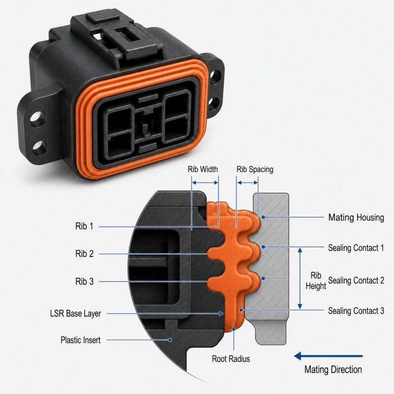
Important geometry includes:
• Rib height
• Rib width
• Rib spacing
• Root radius
• Tip profile
• Silicone thickness beneath the rib
• Distance from the rigid plastic insert
• Available mating clearance
Rib Height
The rib must be high enough to create controlled interference with the mating housing.
However, excessive height can increase assembly force and make the rib more likely to bend, roll or buckle.
Rib Width
A narrow rib can create a concentrated contact band, while a wider rib behaves more like a compression bead.
The correct width depends on silicone hardness, expected compression and available product space.
Rib Spacing
Adjacent ribs need enough space to deform without pressing into each other.
If the ribs are too close, compression of the first rib may mechanically interfere with the next rib.
Root Radius
The base of the sealing rib should transition smoothly into the surrounding silicone.
A sharp root can create a local stress concentration and may also make molding or demolding less stable.
Tip Profile
The top of the rib should create predictable contact with the mating surface.
The final profile should be selected together with the mating geometry rather than by copying a generic gasket shape.
What Happens If the Sealing Ribs Are Too Tall or Too Soft?
A rib that is excessively tall or flexible may deform before it creates stable sealing contact.
Possible symptoms include:
• Rib rolling during assembly
• Sideways silicone displacement
• Excessive insertion force
• Uneven contact around corners
• One rib carrying most of the compression
• Silicone rubbing against the housing
• Permanent deformation after long-term assembly
• Difficult connector mating
This problem becomes more likely when the silicone is very soft, the rib is tall and narrow, or the root has insufficient lateral support.
A design should not assume that a softer seal always produces better waterproof performance.
The rib must be soft enough to conform to the mating surface but stable enough to remain in the intended sealing position.
What Happens If the Sealing Ribs Are Too Low or Too Stiff?
The opposite condition can also create leakage.
If the ribs are too low, the mating housing may reach its final assembly position before enough silicone deformation occurs.
If the silicone or geometry is too stiff, the available assembly force may not compress all sealing ribs correctly.
Possible symptoms include:
• Incomplete contact on one or more ribs
• Leakage at tolerance extremes
• High sensitivity to housing flatness
• Local gaps around corners
• Different leak-test results between assemblies
• A connector that looks assembled correctly but does not seal consistently
The objective is not to make every rib carry exactly the same load.
The objective is to maintain a continuous and repeatable sealing path across realistic part and assembly variation.
Why Must Tolerance Stack-Up Be Included?
Multi-lip seal design cannot be based only on nominal CAD dimensions.
The final rib compression may be affected by:
• Silicone rib height
• LSR dimensional tolerance
• Plastic insert dimensions
• Mating-housing dimensions
• Housing flatness
• Connector alignment
• Assembly-stop position
• Mold-cavity variation
• Temperature
• Long-term dimensional change
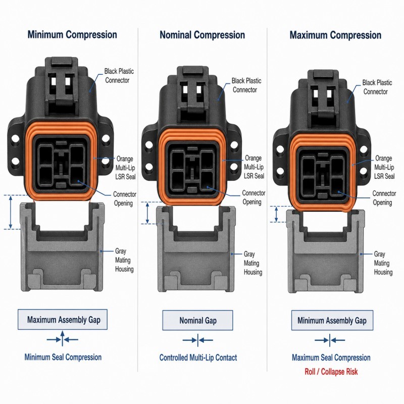
At minimum, engineers should evaluate three conditions.
Minimum Compression Condition
The tolerance combination creates the largest mating gap and the lowest silicone interference.
The seal must still maintain continuous functional contact.
Nominal Compression Condition
The connector and silicone dimensions are close to their nominal values.
This condition is useful for initial design review but cannot be the only approval condition.
Maximum Compression Condition
The tolerance combination creates the smallest gap and the greatest silicone deformation.
The ribs must not roll, cut, collapse or generate unacceptable assembly force.
Where a rigid housing or connector shoulder controls the final closing position, review how compression stops should be designed for LSR overmolded seals.
Multi-Lip Connector Seal DFM Checklist
| DFM Item | What Engineers Should Confirm | Main Risk |
Sealing direction | Radial, axial or another compression direction is defined | Ribs are oriented incorrectly |
Mating surface | Actual housing geometry and tolerance are available | Seal designed without mating data |
Rib height | Minimum and maximum compression are reviewed | Under- or over-compression |
Rib width | Contact band matches hardness and load | Unstable contact |
Rib spacing | Adjacent ribs can deform independently | Rib-to-rib interference |
Root radius | Smooth supported transition is provided | Tear or stress concentration |
Silicone hardness | Material is reviewed with rib geometry | Seal too soft or too stiff |
Plastic support | LSR ribs are supported by a stable insert | Local deformation |
| Parting line | Kept away from critical rib contact surfaces | Flash affects sealing |
| Assembly stop | Final mating position is controlled | Compression depends on force only |
| Validation | Leak, assembly and environmental tests are defined | Sample passes but production fails |
The silicone mold design and tooling review should confirm sealing-rib geometry, insert support, parting-line position, gate, venting and demolding before mold steel is finalized.
How Should Multi-Lip Connector Seals Be Validated?
A multi-lip connector seal should be validated in the final mating assembly rather than only measured as a loose silicone component.
1. Dimensional Inspection
Measure rib height, rib position, silicone boundary, connector position and critical mating dimensions.
2. Assembly Inspection
Confirm that the mating housing reaches its intended final position without rib rolling, cutting or excessive insertion force.
3. Minimum and Maximum Compression Evaluation
Use representative tolerance conditions to confirm that the seal works across the expected assembly range.
4. Leak Testing
Complete the agreed air-leak, pressure-decay, immersion or other waterproof test on the assembled connector.
5. Cross-Section or Contact Analysis
Where appropriate, inspect the compressed sealing profile to understand how individual ribs contact the mating housing.
6. Thermal Cycling
Repeat functional sealing tests after temperature cycling when required by the application.
7. Vibration and Mechanical Testing
Automotive connectors may require evaluation after vibration, cable movement or repeated mating.
8. Multi-Cavity and Pilot Production
Compare multiple cavities and consecutive molding cycles before approving mass production.
A good multi-lip seal is not the one with the largest number of ribs.
It is the one that maintains a stable sealing path across realistic dimensional, assembly and environmental variation.
How SiliconePlus Supports Automotive Connector Seal DFM
SiliconePlus supports custom automotive connector and precision LSR overmolding projects from product review through tooling, sampling, inspection and mass production.
Project support can include:
• Connector and mating-housing review
• Multi-lip sealing-profile DFM
• Silicone hardness evaluation
• Insert-tolerance analysis
• Compression and assembly review
• Parting-line and mold shut-off review
• Gate and venting analysis
• Precision mold development
• LSR injection molding
• Dimensional inspection
• Assembly and waterproof test support
• Pilot-production validation
Specific sealing-rib geometry, compression, tolerance and waterproof acceptance criteria should always be confirmed according to the actual connector, mating housing, silicone grade and agreed test method.
FAQ
Does a Connector Seal Need More Than One Sealing Rib?
Not always. The required number of sealing ribs depends on the connector geometry, mating surface, available space, tolerance, environmental requirement and validation results.
Are More Sealing Ribs Always Better?
No. Additional ribs can increase assembly force and create more geometry that must be molded and controlled. The number of ribs should have a functional reason.
Should All Sealing Ribs Have the Same Height?
Not necessarily. The correct geometry depends on the mating surface and desired compression behavior. Do not copy one universal profile into every connector.
Can Softer Silicone Compensate for Incorrect Rib Geometry?
Not reliably. Material hardness changes deformation and force, but it cannot correct an incorrect mating gap, rib height or assembly stop.
Can a Parting Line Cross a Sealing Rib?
It may sometimes be unavoidable, but flash and mismatch on a critical sealing contact surface increase risk. Parting-line placement should be reviewed during DFM.
Should the Seal Be Tested Before or After Connector Assembly?
Part-level inspection is useful, but final waterproof approval should be based on the assembled connector under defined test conditions.
Conclusion
Reliable multi-lip automotive connector sealing requires coordinated control of:
• Rib height
• Rib width
• Rib spacing
• Root radius
• Silicone hardness
• Mating-housing geometry
• Tolerance stack-up
• Assembly stop
• Parting-line position
• Functional validation
A multi-lip seal should not be designed by simply adding several raised silicone ribs.
Each rib must form part of a controlled sealing system that remains functional from minimum to maximum assembly conditions.