How Should MIM Metal Insert Tolerances Be Managed Before LSR Overmolding?
- Share
- publisher
- SiliconePlus Engineering Team
- Issue Time
- Nov 5,2026
Summary
Metal injection molded (MIM) inserts can change dimension during debinding and sintering, so LSR overmolding tooling must be based on the finished insert—not only its nominal CAD model. This guide explains how to identify critical datums, separate as-sintered and post-machined dimensions, build an overmolding tolerance stack, and define inspection inputs before tooling.
Answer Excerpt
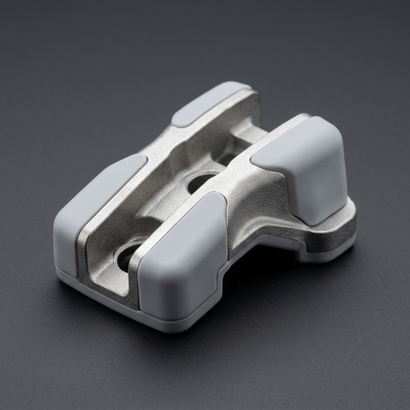
An MIM metal insert should be released to LSR overmolding only after its final post-sintering and any specified finishing dimensions have been defined. The mold must locate the insert from stable, functionally relevant datums—not from an unverified nominal CAD outline. Separate as-sintered dimensions from finish-machined features, identify the surfaces that control sealing, shut-off, alignment and assembly, and include MIM variation, finishing, insert seating, mold location and final LSR geometry in the tolerance review. No single MIM tolerance value should be assumed for every part.
Why Do MIM Metal Inserts Need a Separate Tolerance Review?
Metal injection molding and LSR overmolding are two different manufacturing processes. When they are combined, the dimensional condition of the metal insert becomes an important input to the silicone molding process.
A metal insert may be designed in CAD before the MIM supplier has completed process development. However, the actual part passes through injection molding, debinding and sintering. Additional sizing or machining may also be specified for selected features.
If the LSR mold is designed around nominal CAD dimensions without considering the released metal insert condition, the actual insert may not locate or fit as intended. This can affect silicone coverage, shut-off contact, molded feature position and final assembly fit.
SiliconePlus lists a product for Custom LSR Overmolding for MIM Metal Parts, where liquid silicone rubber is molded directly over a metal insert. The product page does not publish a customer-specific tolerance drawing, so the design principles in this guide should be applied using the actual MIM part and project requirements.
What Happens to MIM Dimensions Before the Insert Reaches the LSR Mold?
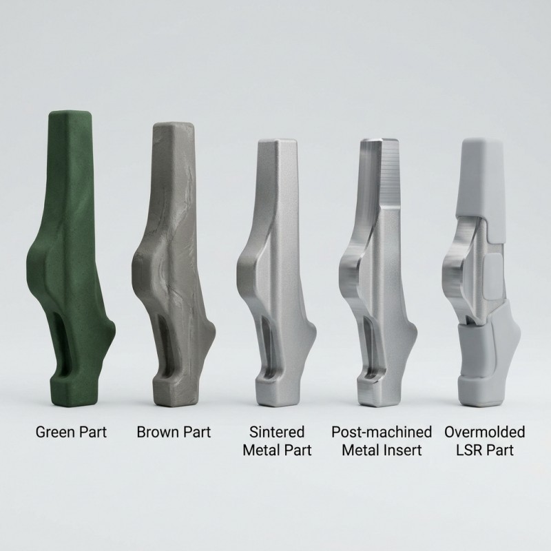
MIM parts do not reach their final metal condition immediately after injection molding.
The process begins with a metal powder and binder feedstock injected into a mold. The molded green part then goes through debinding to remove the binder, followed by sintering to form the consolidated metal component.
Significant dimensional shrinkage occurs during sintering. The MIM process is designed to compensate for this shrinkage, but the actual dimensional capability still depends on the material, part geometry, feature size, process control and supplier capability.
Some components may also require secondary operations such as sizing, machining, grinding or other finishing processes. These operations can change the final dimensions of selected features.
For LSR overmolding, the important reference is therefore the final metal insert condition that will actually enter the silicone molding process—not an earlier green-part model or an outdated nominal drawing.
The MIM drawing revision, finishing status and inspection condition should be confirmed before the LSR mold design is finalized.
MIM stage | Part condition | Information required for LSR overmolding |
| Feedstock injection | Green molded part containing binder | Treat as an intermediate process stage |
Debinding | Binder removal and reduced part strength during processing | Confirm the supplier's controlled process route |
| Sintering | Metal densification and dimensional shrinkage | Obtain the released post-sintering dimensions |
| Secondary finishing | Optional sizing, machining, grinding or other operations | Identify which dimensions are controlled after finishing |
| Incoming inspection | Final insert condition before LSR molding | Use the approved drawing revision and agreed measurement method |
Which MIM Dimensions Matter Most for LSR Overmolding?
Not every metal dimension has the same importance to the overmolding process.
The engineering review should separate dimensions that control the final function from dimensions that have little influence on silicone molding or assembly.
For example, a seating surface may control how the insert rests in the mold. A locating feature may determine its position. A sealing or bonding land may determine where the silicone interface is formed. A shut-off surface may affect the boundary between molded silicone and exposed metal.
The exact critical features depend on the actual component. They should be selected from the part drawing and assembly requirements rather than assigned automatically to every surface.
For projects involving metal with silicone overmolding, the metal insert drawing and the silicone coverage drawing should be reviewed together. This prevents a dimension that appears unimportant on the metal part from becoming a critical feature after overmolding.
| Feature type | Why it may be critical | What to define |
Seating surface | Establishes how the insert rests in the mold or assembly | Datum reference and flatness requirement where applicable |
Locating feature | Controls insert position and orientation | Position, size and measurement method |
Sealing or bonding land | Defines the silicone-to-metal interface | Location, surface condition and required geometry |
| Mold shut-off surface | Controls the silicone coverage boundary | Shut-off reference and permitted variation |
| Exposed metal area | May be needed for electrical, mechanical or assembly functions | Clearly marked no-silicone boundary |
| Final assembly interface | Determines fit with the mating component | Functional dimensions and tolerance relationship |
How Should MIM Datums Be Transferred into the LSR Mold?
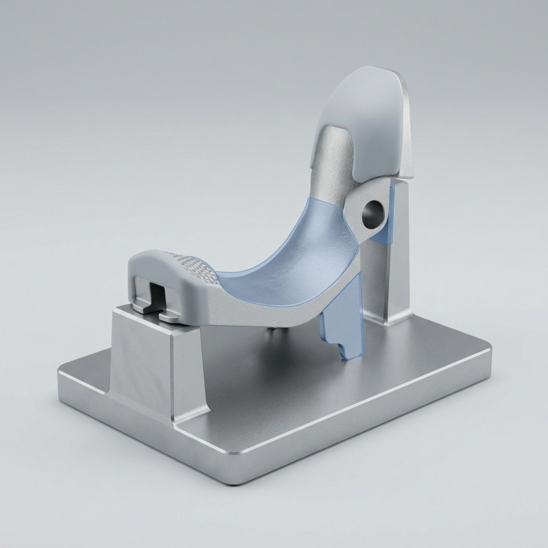
The datum scheme should be established using the final MIM insert and the way the component functions in the assembly.
Where the geometry permits, a primary datum can establish the main seating reference. A secondary datum can control lateral location, while a tertiary datum can control rotation or orientation.
However, this arrangement should not be applied blindly to every MIM component. Small, curved or irregular parts may require datum targets or a dedicated locating fixture based on the actual geometry.
The most important requirement is consistency. The surfaces used to inspect the finished MIM insert should relate logically to the surfaces used to position it in the LSR mold.
The mold designer should also check whether the selected datums are physically accessible and sufficiently stable during insert loading and mold closing.
A datum that exists only as a theoretical CAD reference is not useful if the actual insert cannot be located against it repeatably.
Review the silicone mold design capabilities together with the MIM part drawing so that the metal insert, locating system and silicone cavity can be evaluated as one manufacturing setup.
| Datum reference | Typical purpose | Engineering question |
Primary datum | Establishes the main seating reference | Is the selected surface stable after sintering and finishing? |
Secondary datum | Controls lateral location | Does it relate to the actual assembly interface? |
| Tertiary datum | Controls rotation or orientation | Can the mold fixture locate it without damaging the part? |
| Functional datum | Relates to sealing, fit or mating geometry | Is it included in both inspection and assembly review? |
| Inspection reference | Allows repeatable dimensional measurement | Can the supplier and overmolding manufacturer use the same reference scheme? |
How Should the MIM-to-LSR Tolerance Stack Be Built?
The tolerance review should cover the complete dimensional chain from the incoming MIM insert to the finished overmolded component.
The relevant contributors may include MIM dimensional variation, secondary finishing, insert seating, mold locating accuracy, cavity and shut-off dimensions, and the final molded silicone geometry.
These contributors should not be treated as unrelated tolerances. A small variation in the metal insert may change its position in the mold, which can then shift the silicone coverage boundary or alter the relationship between the molded feature and the final assembly.
The engineering team should identify the functional output that must be controlled first. Examples include a sealing interface, a mating surface, an exposed metal region or a final assembly dimension.
The tolerance calculation method should be agreed according to the project risk. A worst-case stack and a statistical tolerance analysis are not interchangeable, and neither should be selected without understanding the actual process variation and acceptance requirements.
The purpose is not to tighten every dimension. It is to ensure that the dimensions controlling the final function remain within an agreed and manufacturable tolerance range.
| Tolerance contributor | Possible effect | Required review |
MIM dimensional variation | Changes the actual insert envelope | Confirm supplier capability and released dimensions |
Secondary finishing | Changes selected surfaces or features | Identify pre-finish and post-finish dimensions |
Insert seating and loading | Changes the insert's position in the mold | Confirm locating method and repeatability |
Mold locating features | Affect insert alignment | Review fixture and mold reference dimensions |
| Cavity and shut-off geometry | Affect silicone coverage and boundary | Confirm critical cavity dimensions |
| LSR molded geometry | Determines final silicone feature dimensions | Inspect against the approved drawing |
| Final assembly variation | Affects mating fit and functional interfaces | Review the complete tolerance relationship |
When Should a MIM Feature Be Finish-Machined Before Overmolding?
Secondary machining should be considered when an important functional feature cannot be controlled adequately in the agreed as-sintered condition.
Examples may include a critical seating face, a locating feature, a mating surface or a dimension that directly controls the position of the silicone overmold.
This does not mean that every MIM feature should be machined. Applying tight tolerances to non-critical surfaces can increase process complexity and cost without improving the final component function.
The MIM supplier and LSR overmolding manufacturer should therefore agree on which dimensions remain as-sintered and which dimensions require post-sintering finishing.
The final drawing should identify the controlled condition of each critical feature. If a surface is machined after sintering, the LSR mold should be designed around the finished condition rather than the earlier as-sintered geometry.
Any finishing process that changes the insert's surface or dimensional condition should be communicated before sample approval and tooling release.
How Should MIM Surface Finish and Incoming Condition Be Specified?
Dimensional control is only one part of the incoming insert specification.
The drawing should also identify the required surface condition on the areas that contact the LSR, the areas used for mold locating, and the areas that must remain exposed after overmolding.
MIM surface finish should be specified using an agreed measurement method. Surface measurements can be affected by the actual material condition, so the supplier and buyer should confirm how the result will be evaluated.
If the insert has been ground, lapped, burnished, plated or otherwise finished, the final surface condition should be documented rather than assumed from the original MIM drawing.
Contamination, oxidation, oil residue and coating variation should also be controlled where they affect the silicone-to-metal interface.
For the broader incoming metal specification, review metal insert preparation before LSR overmolding. This article focuses on the MIM-specific dimensional and datum requirements, while the preparation guide covers general surface-condition controls.
What Should Buyers Include in an MIM-to-LSR Overmolding RFQ?
A useful RFQ should give the MIM supplier and LSR overmolding manufacturer enough information to evaluate the complete dimensional chain.
The buyer should provide the latest 2D drawing and 3D CAD model, identify the metal material and MIM process route, and clarify whether the dimensions shown represent the as-sintered or finished condition.
Critical datums and dimensions should be marked separately from general dimensions. Any secondary finishing operations, surface finish requirements and measurement methods should also be identified.
The RFQ should then show the intended silicone coverage area, exposed metal regions, mating interfaces and final assembly requirements.
If the metal insert is supplied by another manufacturer, include the supplier's inspection report or representative sample data where available. This helps the overmolding manufacturer assess the actual insert condition before designing the mold.
The clearer the MIM and LSR requirements are at the quotation stage, the easier it is to identify tolerance conflicts before tooling begins.
RFQ information | What to provide | Why it is needed |
Part definition | 2D drawing and 3D CAD model | Establishes the intended geometry |
MIM material | Metal grade and material specification | Confirms the actual substrate |
Process condition | As-sintered or post-finished status | Defines the dimensional reference |
Critical dimensions | Marked functional dimensions and datums | Identifies what must be controlled |
Secondary finishing | Machining, sizing, grinding or other operations if applicable | Confirms the final insert condition |
| Surface specification | Surface finish and inspection method | Aligns incoming quality requirements |
Silicone coverage | Marked LSR coverage and exposed metal zones | Defines the overmolding boundary |
| Assembly interface | Mating part drawings and assembly conditions | Connects insert tolerances to final fit |
| Validation requirements | Inspection and functional acceptance criteria | Defines sample approval |
| Production demand | Prototype quantity and estimated production volume | Supports tooling and process planning |
How Should MIM Inserts Be Inspected Before LSR Tooling Is Released?
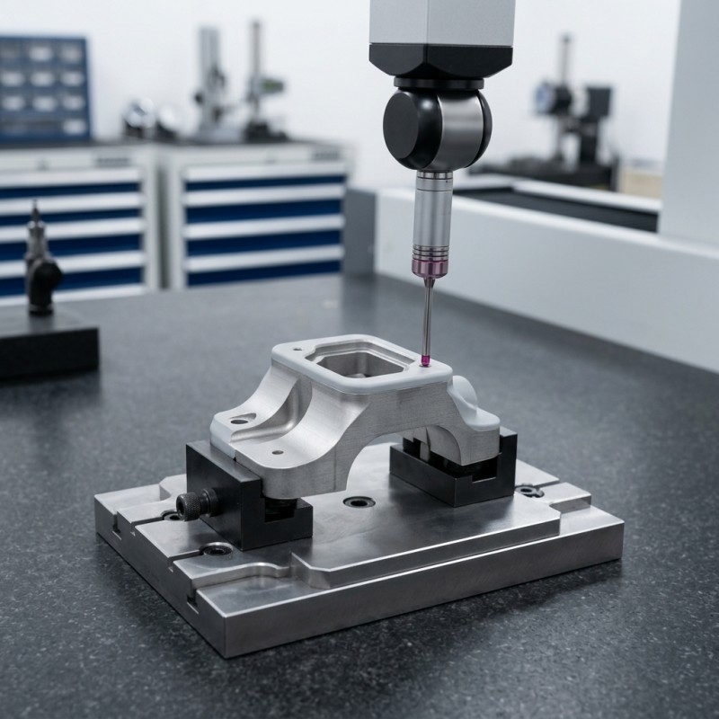
The first inspection should take place after the MIM supplier has completed the agreed sintering and finishing operations.
The inspection report should use the same datum scheme as the approved drawing. Critical dimensions, flatness where required, locating features and relevant surface conditions should be checked using the agreed measurement method.
The LSR overmolding team should then review representative inserts in the proposed locating setup. The purpose is to confirm that the real insert can be loaded and positioned as intended without relying on an unverified nominal model.
During mold trials, the finished overmolded component should be checked for silicone position, coverage boundaries, exposed metal areas, critical dimensions and assembly fit.
The inspection plan should distinguish incoming metal insert measurements from final overmolded part measurements. This helps identify whether a dimensional issue originates in the MIM insert, the locating setup, the mold or the silicone molding process.
For projects involving liquid silicone injection molding, the inspection and process review should be agreed before the production tooling is finalized.
| Inspection stage | Inspection focus | Record to retain |
Incoming MIM insert | Final dimensions, datum features and surface condition | Incoming inspection report |
Insert locating review | Seating and repeatability in the proposed fixture | Setup review record |
| Mold trial | Insert position, silicone coverage and shut-off boundary | Trial inspection record |
| Finished component | Critical dimensions, exposed metal and assembly fit | First-article inspection report |
| Sample approval | Agreed drawing revision and acceptance criteria | Customer sample approval record |
Frequently Asked Questions
Does every MIM metal insert need secondary machining before LSR overmolding?
No. Secondary machining is only necessary when a critical feature cannot meet the agreed requirement in its as-sintered condition. The decision should be based on the actual material, geometry, process capability and functional dimensions.
Can the nominal MIM CAD model be used directly for LSR mold design?
The CAD model is a design reference, but it should be checked against the final released MIM insert condition. The LSR mold should account for the actual post-sintering and any specified post-machining dimensions.
Should every dimension on a MIM insert drawing have a tight tolerance?
No. Tight tolerances should be concentrated on features that control location, sealing, mating fit, shut-off or another defined function. Non-critical dimensions should not be over-specified without a functional reason.
Who should define the datum scheme for an MIM insert used in LSR overmolding?
The product designer, MIM supplier and LSR overmolding manufacturer should review the datum scheme together. It should relate to the final insert condition, the mold locating method and the component's assembly requirements.
When should MIM dimensions be inspected?
Critical dimensions should be checked after the agreed sintering and finishing operations, before LSR overmolding. The finished overmolded component should then be inspected separately for silicone position, coverage, dimensional requirements and assembly fit.
Conclusion
Reliable LSR overmolding on MIM metal inserts starts with a clear understanding of the final metal part condition.
The key is to separate nominal CAD dimensions from actual post-sintering and post-finishing dimensions, identify the functional datums, and review the complete tolerance chain from the MIM insert to the finished overmolded component.
Not every feature needs a tight tolerance, and no universal MIM tolerance should be applied without reviewing the actual material, geometry and supplier capability.
For OEM projects, the most effective approach is to align the MIM drawing, datum scheme, finishing requirements, LSR mold references and final assembly requirements before tooling begins.
Discuss Your MIM-to-LSR Overmolding Project
Developing a metal injection molded component that requires integrated LSR overmolding?
SiliconePlus can review the proposed metal insert, silicone coverage, locating references, mold feasibility and dimensional requirements based on your project drawings and samples.
Send your 2D drawing, 3D CAD file, MIM material information, finishing requirements, critical dimensions and intended silicone coverage to contact SiliconePlus for a project review.
The proposed manufacturing route, tooling requirements and inspection criteria will be evaluated according to the actual component design and application requirements.