How Should LSR Seal Beads Be Designed for Fuel Cell Bipolar Plates?
- Share
- publisher
- SiliconePlus Engineering Team
- Issue Time
- Nov 4,2026
Summary
A practical guide to LSR overmolded seals on metal fuel cell bipolar plates. Learn how to coordinate perimeter and manifold sealing paths with stack compression, plate flatness, exposed flow fields, material validation and sample inspection.
Answer Excerpt
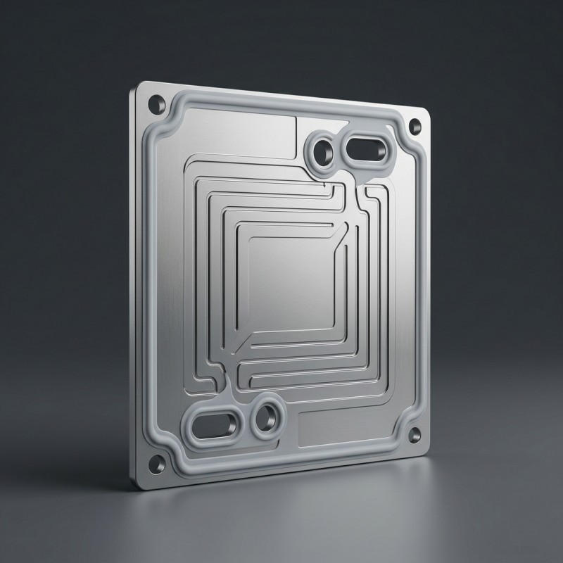
An LSR overmolded seal for a metal fuel cell bipolar plate should be designed as part of the final stack interface—not as an isolated bead. Define the perimeter and manifold sealing paths against the mating components, then size the bead around the specified stack gap and compression window. At the same time, preserve the flow-field channels, gas and coolant openings, electrical contact regions, and plate locating features. The correct geometry can only be established from the customer's plate drawings, substrate condition, stack assembly data, operating media, and validation requirements.
Why Is Bipolar Plate Seal Design a Stack-Level Problem?
In a PEM fuel cell stack, bipolar plates separate adjacent cells and provide flow fields for reactant gases. Gaskets or integrated sealing structures help create the boundaries required to limit leakage around the membrane electrode assembly and designated manifold regions.
A seal bead may look continuous on an isolated metal plate and still be unsuitable after assembly. Its height, location, and compression can affect the final stack gap and the contact conditions at the sealing interface.
For an overmolded design, liquid silicone rubber is molded directly onto defined sealing areas of the metallic substrate. Unlike a loose gasket installed during assembly, the integrated bead has a fixed position relative to the metal insert. Plate flatness, locating datums, surface condition, and mating stack geometry therefore become important design inputs.
The SiliconePlus product page for the Custom LSR Overmolded Fuel Cell Bipolar Plate Seal describes a customer-supplied metallic substrate, molded perimeter and manifold sealing beads, and exposed functional zones. The final geometry and material selection remain subject to the customer's stack specification and validation requirements.
Which Areas Should the LSR Seal Cover—and Which Must Stay Exposed?
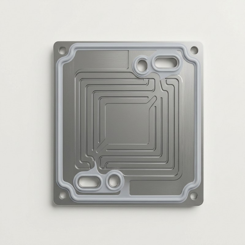
The first design task is to separate the intended silicone coverage from the functional areas that must remain exposed.
The sealing layout should be developed from the bipolar plate drawing and the mating stack structure. Depending on the plate architecture, the LSR may form a perimeter sealing path and designated sealing beads around manifold regions.
However, silicone should not be allowed to cover flow-field channels, gas passages, coolant openings, electrical contact lands, or locating features that must remain functional.
Do not define these areas with a general instruction such as “keep this area clear.” Mark them on the drawing using identifiable datums, boundaries, and inspection requirements. This makes the coverage map useful for DFM review, mold design, sampling, and production inspection.
| Plate area | Intended treatment | Engineering review |
External perimeter sealing land | Defined LSR sealing path where required | Confirm continuity, location and mating contact |
Manifold sealing land | LSR bead around designated sealing regions | Confirm port alignment and separation of sealing boundaries |
Flow-field channels | Remain exposed | Check that no silicone or flash enters the channels |
| Gas and coolant openings | Remain open unless the drawing specifies otherwise | Confirm opening geometry and mold shut-off |
| Electrical contact regions | Remain exposed | Confirm that silicone does not cover conductive surfaces |
| Locating and alignment features | Follow the approved drawing | Confirm datum access and stack alignment |
How Should Perimeter and Manifold Sealing Paths Be Laid Out?
The perimeter and manifold sealing paths should be defined together with the final stack architecture.
For the external perimeter, the design should identify a continuous sealing route that matches the intended mating surface. Corners, transitions, and changes in direction require particular attention because the sealing path must remain consistent with the available contact area.
Where the bipolar plate design requires sealing around a manifold opening, define the bead boundary in relation to the port and its adjacent flow passages. Avoid assuming that every opening needs the same bead profile or that all sealing paths can be connected into one continuous feature.
The designer should also review the distance between adjacent sealing paths, the available metal lands, and the space required for mold shut-off. These details determine whether the intended silicone coverage can be manufactured without interfering with other plate functions.
For projects involving metal substrates, review the manufacturing considerations for metal with silicone overmolding before finalizing the coverage layout.
How Should Bead Cross-Section Match the Stack Compression Window?
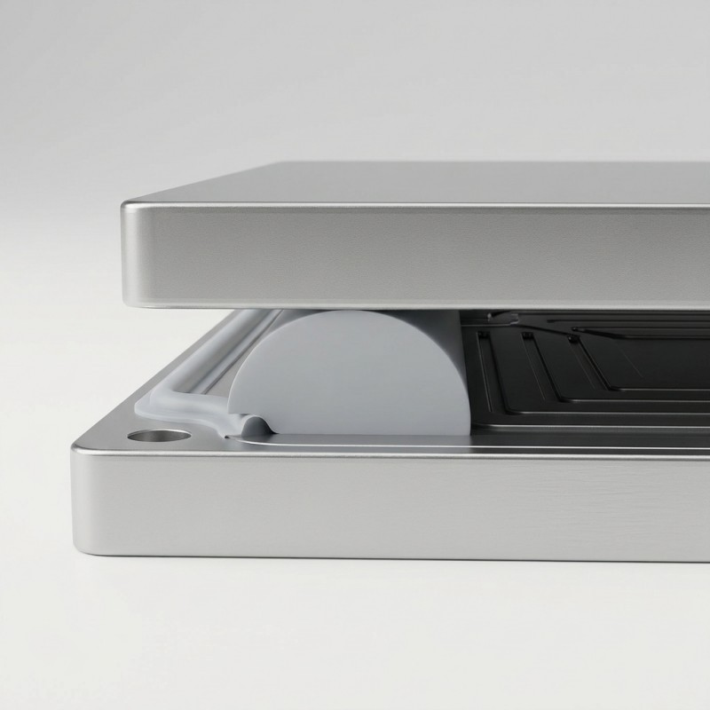
The free height, width, cross-section, and position of an LSR bead must be considered together with the assembled stack gap.
A bead that is too low may not develop sufficient contact against the mating surface. A bead that is too high may create excessive local compression or affect the dimensional relationship between adjacent stack components.
The design should therefore be based on the customer's actual assembly conditions rather than a generic silicone bead dimension or a universal compression ratio.
Important inputs include the nominal stack gap, the expected tolerance range, the flatness of the metal plate, the mating surface geometry, and the specified clamping conditions.
The engineering review should consider both nominal and worst-case conditions. A bead that appears suitable at nominal dimensions may behave differently when plate flatness, insert position, and assembly tolerances are considered together.
Where perimeter and manifold sealing regions have different surrounding geometries, their compression conditions should be evaluated as part of the same stack assembly rather than as unrelated features.
| Design input | Why it matters | What should be confirmed |
Nominal stack gap | Establishes the available assembled space | Customer assembly drawing |
Bead free height and width | Influences the contact condition after assembly | Approved bead cross-section |
Metal plate flatness | Affects local gap variation | Substrate drawing and inspection criteria |
| Mating surface geometry | Defines the actual contact interface | Mating component drawing |
| Clamping conditions | Influence stack compression and contact pressure | Customer assembly specification |
| Dimensional tolerances | Affect worst-case compression | Tolerance stack-up review |
How Can the Metal Plate Be Supported During LSR Overmolding?
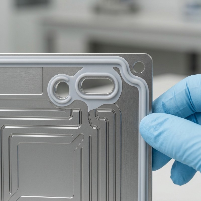
A formed metal bipolar plate may be relatively thin and sensitive to handling or deformation. The overmolding process must therefore be reviewed with the substrate geometry and its support conditions in mind.
Insert positioning should use stable locating datums that correspond to the approved drawing. The plate should be supported at suitable locations so that it remains correctly positioned during molding without placing unnecessary loads on sensitive functional areas.
The DFM review should also consider substrate flatness variation, surface coating condition, and the relationship between the metal insert and the mold shut-off surfaces.
The metal surface must be identified before material and bonding decisions are made. A selected LSR compound should not be assumed to bond chemically to every metal or coating. Surface preparation, material compatibility, and any required mechanical retention must be evaluated for the actual substrate.
For additional background, review the requirements for metal insert preparation before LSR overmolding. The correct preparation route depends on the actual metal, coating, and project specification.
How Should Mold Shut-Off Protect Flow Channels and Contact Lands?
The mold shut-off design must follow the approved silicone coverage map.
For a fuel cell bipolar plate, the critical boundaries may include the edges of flow-field channels, manifold openings, designated electrical contact lands, and locating features. The shut-off surfaces must prevent unintended silicone coverage while maintaining the intended bead geometry.
Insert position, substrate flatness, and mold alignment should be reviewed together. A small change in the position of the metal insert can affect the relationship between the silicone bead and a nearby functional boundary.
Gate and vent locations should also be considered in relation to the sealing path and exposed areas. The objective is to fill the intended sealing regions while controlling flash and avoiding material intrusion into functional openings.
These requirements should be translated into drawing-based inspection criteria. A visual check of the main bead alone is not sufficient if the flow channels, ports, or electrical contact surfaces also have critical acceptance requirements.
The broader design principles for no-silicone zones in LSR overmolding are relevant here, but the bipolar plate drawing must define the actual protected regions for each project.
Which LSR Material Inputs Need Fuel-Cell-Specific Validation?
LSR material selection should be based on the actual operating environment of the fuel cell stack.
The engineering review should identify the metal substrate and any surface coating, as well as the media that may contact the sealing material. Depending on the application, these may include hydrogen, humidified gases, and coolant.
Operating temperature, pressure, exposure duration, cleanliness requirements, and the customer's material qualification criteria should be documented before a material is finalized.
A silicone grade suitable for one sealing application should not automatically be assumed suitable for every fuel cell environment. Chemical compatibility, compression behavior, aging, and the condition of the silicone-to-metal interface must be evaluated under the relevant project conditions.
SiliconePlus provides liquid silicone injection molding and custom LSR manufacturing services. The material and process selection for a bipolar plate project still needs to be assessed against the customer's actual substrate, operating media, and validation requirements.
How Should Samples Be Inspected and Validated?
Sample evaluation should cover the metal substrate, the molded sealing structure, and the assembled interface.
Before molding, confirm the substrate material, surface condition, coating information, dimensions, and flatness against the approved drawing.
After molding, inspect the bead position, cross-section, continuity, and edge condition. The designated flow channels, manifold openings, and electrical contact areas should also be checked for unintended silicone coverage or flash.
The next step is to review the part in the intended mating assembly. Confirm the alignment of the sealing paths and evaluate the compression condition against the customer's specified stack gap and clamping requirements.
Functional leakage testing should use the actual media, pressure conditions, and acceptance criteria defined by the customer. Additional environmental or durability tests should be agreed according to the intended application.
These are recommended engineering validation stages. They should not be interpreted as a claim that a particular fuel cell stack or operating condition has already been qualified by SiliconePlus.
| Stage | Inspection or validation item | Acceptance basis |
Incoming substrate | Material, coating, surface condition, dimensions and flatness | Customer-approved drawing and material requirements |
Molded bead | Position, cross-section, continuity and surface condition | Approved LSR component drawing |
Functional zones | Flow channels, manifold openings and contact areas | Coverage map and no-silicone-zone requirements |
| Assembly fit | Alignment, mating surfaces and stack gap | Customer assembly specification |
| Functional testing | Gas or coolant leakage, where applicable | Customer-defined test method and acceptance criteria |
| Durability evaluation | Media exposure, aging and environmental conditions, where required | Project qualification plan |
What Should Buyers Include in an LSR Bipolar Plate RFQ?
To evaluate a custom LSR overmolding project for a fuel cell bipolar plate, buyers should provide enough information to review the substrate, sealing geometry, and final assembly conditions.
The RFQ package should include:
- 2D engineering drawings and 3D CAD files of the bipolar plate
- Metal substrate material, thickness, and surface coating information
- Substrate flatness and dimensional tolerance requirements
- A drawing or marked-up model identifying the proposed LSR coverage
- Perimeter and manifold sealing bead requirements
- Flow-field channels, ports, electrical contact lands, and other protected areas
- Mating component drawings and stack assembly information
- Nominal stack gap and clamping conditions
- Operating gas, coolant, temperature, and pressure requirements
- Target leakage criteria and required validation methods
- Prototype quantity and estimated production volume
Buyers should also identify whether the metal bipolar plate will be supplied by the customer or whether additional substrate-related services are required.
The current product scope describes LSR overmolding, DFM review, tooling, sampling, and sample inspection. Metal plate forming, conductive coating, fuel cell stack assembly, and complete system qualification should be identified separately if they are required.
Providing these details helps the engineering team assess whether the proposed seal layout and overmolding process are suitable for the intended project.
Frequently Asked Questions
Is an LSR overmolded bipolar plate seal the same as a loose gasket?
No. In an overmolded design, LSR is molded directly onto defined sealing areas of the metallic bipolar plate. A loose gasket is a separate component installed during assembly. The two approaches have different positioning, manufacturing, and assembly requirements.
Can LSR cover the flow-field channels of a bipolar plate?
The intended flow-field channels and designated gas or coolant passages should remain open unless the approved drawing specifies otherwise. The LSR coverage map and mold shut-off design must protect these functional areas.
Can SiliconePlus recommend a universal bead height or compression ratio?
No universal value should be applied without the plate drawing and stack assembly data. Bead geometry must be reviewed against the mating surfaces, stack gap, plate flatness, tolerances, and clamping conditions.
Can the same LSR material be used for every hydrogen fuel cell application?
Not automatically. Material suitability depends on the actual gas, coolant, temperature, pressure, substrate surface, and qualification requirements. The selected material must be evaluated for the specific application.
Does the LSR overmolding service include complete fuel cell stack qualification?
Not automatically. The product scope focuses on the LSR overmolding portion, including DFM review, tooling, and sampling. Complete stack assembly and system qualification remain subject to the agreed project scope and the customer's validation programme.
Conclusion
An LSR overmolded fuel cell bipolar plate seal must be designed around the complete stack interface rather than the silicone bead alone.
The perimeter and manifold sealing paths, bead cross-section, metal plate flatness, stack compression, and protected functional areas all need to be considered together. Material compatibility and final sealing performance must also be validated against the actual operating environment.
For OEM and engineering teams, the most effective starting point is a clear set of plate drawings, substrate information, sealing requirements, and stack assembly conditions. These inputs allow the overmolding design to be reviewed before tooling and sampling begin.
Discuss Your Fuel Cell Bipolar Plate Project
Developing a metal bipolar plate that requires an integrated LSR sealing structure?
SiliconePlus can review the proposed overmolding design, including seal placement, bead geometry, metal insert positioning, material compatibility, tooling feasibility, and prototype requirements.
Send your 2D drawings, 3D CAD files, substrate and coating information, stack assembly conditions, and target validation requirements to contact SiliconePlus for a project review.
The proposed manufacturing scope and final acceptance criteria will be assessed according to your component design and project specifications.