How Should LSR Overmolded Wearable Charging Contacts Be Sealed Without Affecting Electrical Connection?
- Share
- publisher
- SiliconePlus Engineering Team
- Issue Time
- Oct 9,2026
Summary
LSR overmolding can integrate silicone sealing around wearable charging contacts while keeping conductive pads accessible. This guide explains contact-height control, sealing geometry, repeated docking, sweat exposure, insert positioning and inspection for custom smartwatch and wearable charging interfaces.
Answer Excerpt
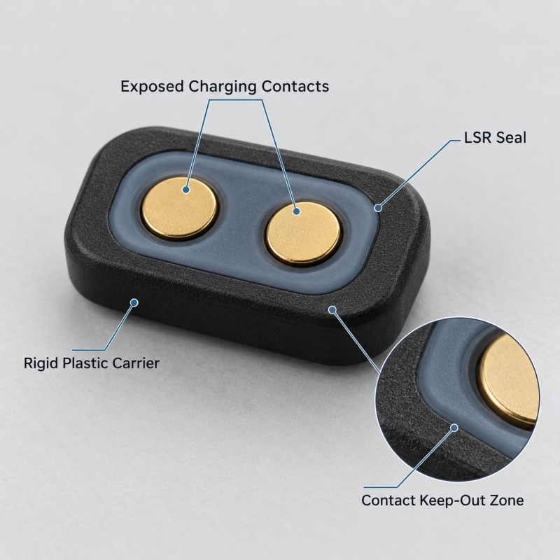
An LSR overmolded wearable charging interface must keep electrical contacts accessible while creating a controlled silicone sealing structure around the areas that require moisture protection.
The silicone cannot simply cover every exposed surface. Charging pads must remain conductive, the charger must reach its intended contact position, and the surrounding housing must maintain the required sealing performance.
For smartwatches, fitness trackers, smart rings and other compact rechargeable devices, engineers should evaluate:
• Electrical contact exposure
• Contact height and position
• Silicone coverage boundary
• Sealing-lip geometry
• Charger docking direction
• Mechanical interference
• Repeated docking wear
• Sweat and moisture exposure
• Plastic or metal insert tolerance
• LSR molding consistency
• Final assembly validation
The main engineering challenge is balancing three functions: reliable electrical connection, controlled environmental protection and repeatable mechanical assembly.
An LSR charging interface seal must be designed as part of the complete charging system rather than approved only as a loose molded component.
Why Are Wearable Charging Interfaces Difficult to Seal?
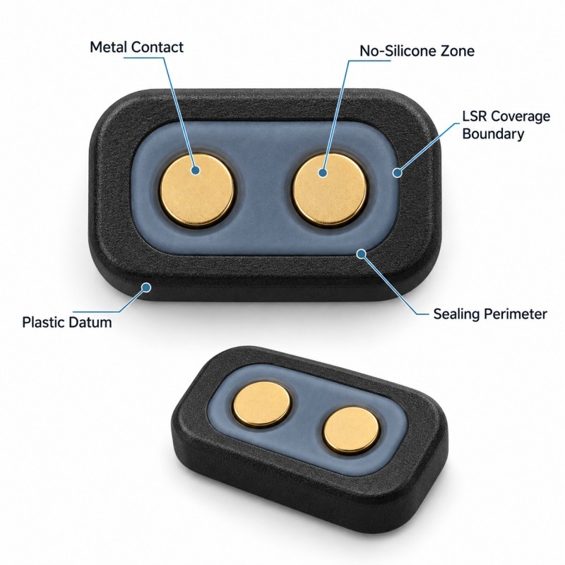
A wearable charging interface combines electrical and mechanical functions in a very small space.
Unlike a conventional housing gasket, the charging area may need to remain externally accessible during normal use.
Depending on the device, charging may involve exposed metal pads, spring-loaded charging contacts, a magnetic docking arrangement or another customer-specific contact system.
These features create several design challenges.
First, the conductive contact surfaces must remain accessible.
Second, moisture must be controlled so that it cannot enter sensitive internal regions through unintended gaps.
Third, repeated attachment and removal of the charger must not damage the surrounding silicone.
Fourth, the final housing and charging accessory must fit together without excessive interference.
A reliable solution does not necessarily keep every exposed metal contact dry. Some charging designs intentionally expose contact pads to the environment.
The sealing objective must therefore be clearly defined: prevent moisture ingress into the device, protect selected interfaces, or support another specified environmental requirement.
The appropriate design depends on the complete product architecture.
1. Define the Charging Contact Keep-Out Zone
The first design requirement is to establish exactly where silicone is permitted.
For a typical wearable charging interface, the drawing should distinguish:
• Exposed conductive contact areas
• Rigid plastic carrier surfaces
• Silicone sealing regions
• Charger alignment features
• Housing mating surfaces
• Functional assembly clearances
A silicone over plastic structure may integrate a flexible sealing lip directly onto a rigid charging-interface carrier.
However, the molded silicone must stop at the approved boundary.
It should not cover the conductive metal contact, restrict the intended contact area or create unwanted interference with the charging accessory.
Critical dimensions may include:
• Exposed contact diameter or outline
• Silicone-to-contact spacing
• Contact center position
• Silicone termination location
• Mating-face clearance
• Plastic carrier datum position
The design should identify these features in the 2D drawing rather than relying only on a colored 3D rendering.
If the contact exposure changes during production, the finished charging interface may become inconsistent even when the silicone itself looks acceptable.
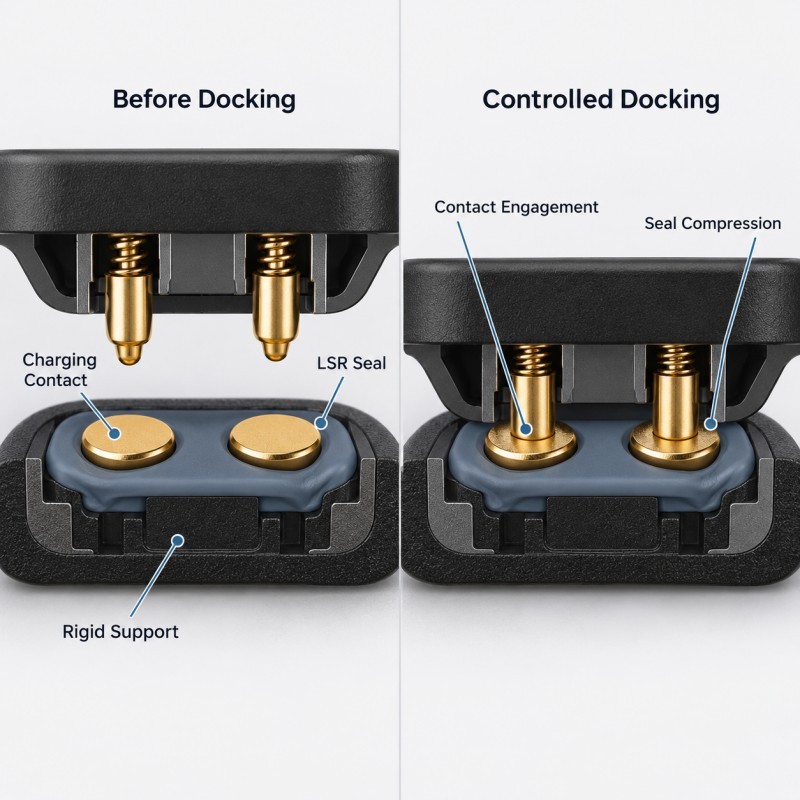
2. Control Seal Compression Without Changing Electrical Contact Engagement
The charging interface may contain two different mechanical contact systems.
One is the conductive connection between the device and charger.
The other is the silicone sealing or cushioning interface.
These two systems should not interfere with each other.
If the silicone feature is too tall or too stiff, it may prevent the charging contacts from reaching their required engagement position.
If the silicone is too low or insufficiently supported, it may not provide the intended sealing or cushioning function.
Engineers should review:
• Silicone free height
• Final assembly gap
• Contact protrusion height
• Charging-pin travel, where applicable
• Charger alignment
• Silicone hardness
• Contact force requirements
• Housing stiffness
• Assembly tolerance stack-up
Where a defined mechanical closing position is required, compression stops can help prevent excessive deformation of the silicone.
However, a rigid stop must be designed around the complete charging and sealing arrangement.
A stop that protects the silicone but prevents the conductive contacts from engaging is not a successful solution.
Electrical contact force and silicone sealing compression should be verified separately and then checked together in the final assembly.
3. Repeated Charger Docking Must Not Damage the Silicone Edge
Wearable devices may be connected to and removed from their chargers many times during normal service.
This repeated movement can create local mechanical stress near the charging interface.
Depending on the charger design, the silicone may experience:
• Sliding contact
• Local compression
• Edge rubbing
• Repeated contact with a rigid charger surface
• Misaligned docking
• Side loading during removal
• Contamination-related abrasion
These loads can damage a thin or unsupported silicone termination.
Potential failure symptoms include:
• Edge lifting
• Local tearing
• Visible surface wear
• Permanent deformation
• Changes in charger seating
• Unstable sealing contact
The silicone termination should therefore be positioned away from direct sliding or scraping contact where the product geometry allows it.
Rounded transitions and adequate support from the rigid insert may improve resistance to handling-related damage.
The required durability should be validated under the customer's actual charger design, docking motion and cycle requirements.
A successful first connection does not demonstrate repeatable performance over the intended service life.
4. Sweat and Moisture Paths Must Be Analyzed Separately From Contact Exposure
Wearable charging interfaces may be exposed to sweat, skin oils, cleaning residues, condensation and ordinary environmental moisture.
These conditions create two different engineering concerns.
The first is corrosion or contamination of exposed conductive contact surfaces.
The second is moisture entering the device through an unintended path around the charging-interface assembly.
An LSR sealing structure may help control the second concern when the seal interrupts the actual ingress path.
However, silicone surrounding a contact does not automatically prevent corrosion of the exposed metal surface.
Engineers should identify:
• Exposed contact area
• Housing-to-carrier joint
• Silicone-to-substrate interface
• Potential capillary gaps
• Contact-pad recesses
• Contamination collection points
• Cleaning and drying conditions
• Internal moisture-sensitive areas
A continuous silicone boundary should be positioned around the intended housing interface rather than placed arbitrarily close to the conductive pads.
If moisture is permitted to reach the exposed charging pads, their material, plating, cleaning behavior and electrical reliability must be evaluated separately by the device engineering team.
No waterproof rating should be inferred from the presence of LSR alone.
5. Insert Positioning and Mold Shut-Off Must Protect Metal Contacts
The charging interface may combine a rigid plastic carrier, metal contacts and a flexible printed circuit.
Each insert must remain in the correct position during LSR injection molding.
A small movement may change:
• Silicone coverage position
• Exposed contact size
• Contact-to-seal clearance
• Silicone wall thickness
• Contact height
• Housing fit
• Final sealing geometry
The mold must also prevent liquid silicone from entering critical conductive areas.
Important tooling considerations include:
• Stable carrier locating surfaces
• Metal contact dimensional variation
• Insert flatness
• Mold shut-off geometry
• Gate location
• Venting
• Parting-line position
• Flash-sensitive boundaries
Excessive mold contact pressure should not be used to compensate for poorly supported inserts if it risks deforming the metal or plastic structure.
For interfaces involving FPC, the flexible circuit should be supported without damaging contact pads, copper traces or critical bending regions.
A reliable design should preserve both the electrical function and the required silicone geometry through repeated production cycles.
6. Select Silicone Materials Based on the Real Wearable Environment
The choice of LSR material should reflect the function of the charging interface and its expected operating environment.
Important considerations may include:
• Silicone hardness
• Compression recovery
• Tear resistance
• Surface friction
• Substrate compatibility
• Exposure to sweat and cleaning agents
• Temperature range
• Color and appearance
• Electrical insulation requirements
• Required aging performance
A softer silicone is not automatically a better sealing solution.
A very soft and thick feature may create unwanted interference during docking.
A harder or poorly supported thin lip may fail to provide sufficient deformation at the mating interface.
Material selection should therefore be reviewed with actual seal geometry and final assembly conditions.
If the project has specific electrical, chemical-resistance or regulatory requirements, the selected material grade and finished component must be validated against those specifications.
Material claims should not be inferred from a generic silicone description.
7. Validate Charging and Sealing as Two Separate Functions
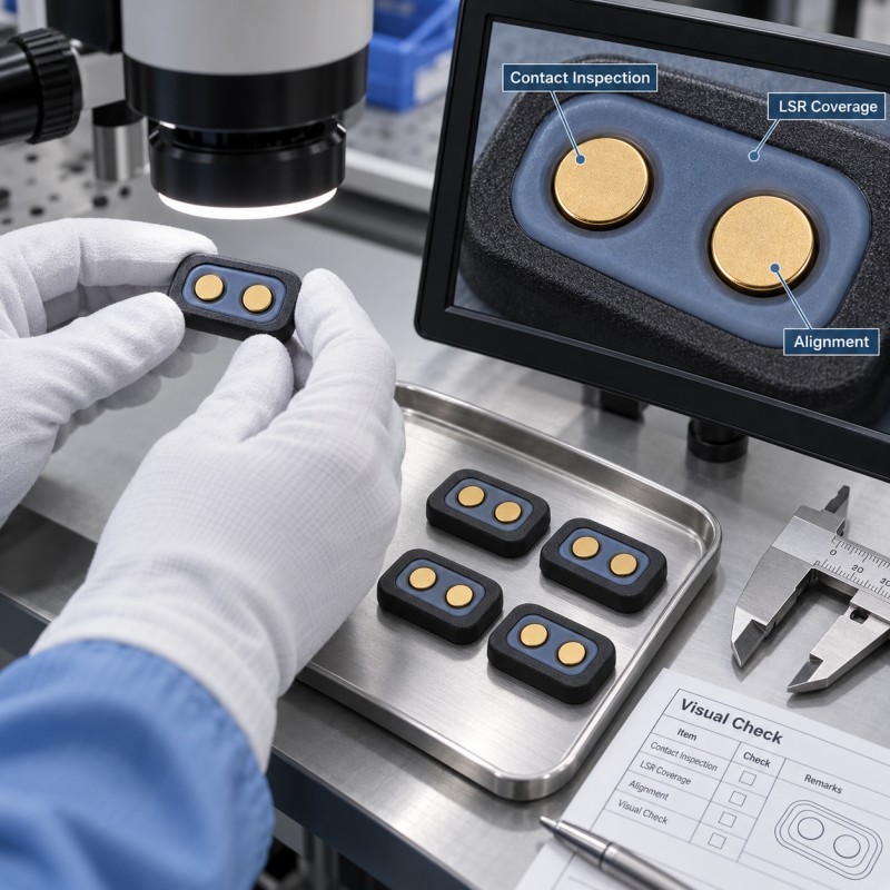
A charging-interface seal should not be approved based only on appearance, dimensional inspection or a single successful charging attempt.
The test plan should distinguish electrical contact performance from environmental sealing performance.
Electrical and mechanical validation may include:
• Contact position measurement
• Charger engagement verification
• Contact resistance testing by the customer
• Charging continuity checks
• Repeated docking and removal
• Contact-force evaluation
• Alignment inspection
• Silicone edge wear inspection
Environmental and sealing validation may include:
• Silicone boundary inspection
• Assembly leak testing
• Water or sweat-exposure testing
• Thermal cycling
• Humidity exposure
• Cleaning-agent exposure
• Inspection after repeated use
The final test conditions should define the actual product orientation, exposure level, sample quantity, test duration and acceptance criteria.
For a charging interface with exposed conductive pads, the customer should also determine how contact contamination is assessed after the relevant environmental exposure.
Passing a sealing test does not automatically prove electrical contact reliability.
Likewise, successful charging does not prove that the surrounding housing interface is waterproof.
Both requirements should be approved on the actual or representative device assembly.
| Design Item | Main Risk | Engineering Control | Validation |
Contact exposure | Silicone covers conductive pad | Defined keep-out boundary | Optical inspection |
Contact height | Charger cannot engage correctly | Datum and height control | Docking test |
Seal compression | Under- or over-compression | Lip geometry and assembly gap | Assembly inspection |
Repeated docking | Silicone edge wear or tearing | Edge position and support | Cycle test |
Sweat exposure | Contact contamination or ingress | Exposure-path review | Environmental testing |
Plastic carrier | Dimensional variation | Insert locating and flatness control | Dimensional inspection |
Metal contact | Flash or unwanted film | Mold shut-off control | Contact-surface inspection |
| FPC transition | Flexing or handling damage | Controlled support and coverage | Bend and assembly test |
| Contact reliability | Unstable electrical connection | Contact geometry and mating design | Electrical function test |
| Environmental sealing | Moisture enters housing | Continuous functional sealing path | Final assembly leak test |
When Is an Integrated LSR Overmolded Charging Interface Seal Suitable?
An integrated LSR sealing structure may be suitable when the silicone must remain accurately positioned around a small charging interface.
Potential applications include:
• Smartwatch charging modules
• Fitness tracker charging contacts
• Compact wearable charging interfaces
• Smart ring charging structures
• Portable monitoring devices
• Rechargeable personal-care electronics
Compared with a separate loose gasket, an integrated structure may reduce gasket-placement variation and help maintain a repeatable sealing geometry.
However, integrated overmolding is not automatically the best method for every design.
The decision should consider:
• Plastic and metal insert geometry
• Charging contact arrangement
• Silicone coverage requirements
• Assembly process
• Docking motion
• Production volume
• Tooling feasibility
• Inspection requirements
SiliconePlus offers a custom LSR overmolded charging interface seal for wearable devices, with silicone molded around customer-specific plastic, metal-contact or FPC structures while leaving the required conductive surfaces exposed.
This is a custom manufacturing service for silicone sealing components, not a supply of complete smartwatch charging electronics or finished wearable devices.
What Should Buyers Provide Before Tooling and Quotation?
A useful RFQ for a wearable charging-interface seal should include the actual mechanical and electrical interface requirements.
Recommended project information includes:
• 2D and 3D charging-interface drawings
• Plastic carrier material
• Metal contact material and surface finish
• Contact dimensions and exposed areas
• FPC details, if applicable
• Silicone coverage boundary
• Required sealing lip geometry
• Charging accessory mating geometry
• Contact engagement or travel requirement
• Available assembly clearance
• Operating temperature and exposure environment
• Sweat and cleaning requirements
• Waterproof or environmental test criteria
• Repeated docking requirements
• Inspection and acceptance criteria
• Estimated order quantity
• Annual production forecast
When possible, the engineering team should also review the mating charging accessory and the surrounding wearable housing.
These inputs help determine whether the intended silicone structure can be molded consistently without compromising the electrical or mechanical functions of the interface.
Frequently Asked Questions
Can Silicone Be Overmolded Around Exposed Smartwatch Charging Contacts?
Yes, depending on the metal contact, plastic carrier, insert positioning and mold shut-off design. The conductive surfaces must remain exposed where electrical connection is required, while silicone is molded only in approved sealing or protection areas.
Can an LSR Seal Interfere With Charging Contact Force?
Yes. Excessive silicone height, stiffness or assembly interference may prevent the charging accessory from reaching its intended contact position. Contact engagement and silicone compression should be checked together in the final assembly.
Does LSR Overmolding Prevent Sweat Corrosion on Charging Pads?
Not automatically. Silicone may help seal selected housing interfaces, but exposed conductive pads still require appropriate metal surface selection, contamination control and environmental validation.
Can LSR Charging Seals Support Waterproof Wearable Devices?
They can form part of a waterproof design, but the achieved performance depends on the complete sealing path, contact architecture, assembly tolerances and customer-defined testing. The silicone component alone does not establish an IP rating.
What Should Be Tested After Repeated Charging Cycles?
Depending on the product, testing may include silicone edge wear, contact alignment, contact resistance, charging continuity, assembly fit, sealing condition and environmental performance after repeated docking and removal.
Conclusion
A reliable wearable charging-interface seal must support electrical connection and environmental protection without allowing one function to interfere with the other.
The design should control:
• Conductive contact exposure
• Silicone coverage boundaries
• Contact height
• Seal compression
• Charger docking geometry
• Insert positioning
• Mold shut-off
• Silicone edge durability
• Sweat and moisture exposure
• Electrical and environmental validation
The most important principle is that the silicone should protect the intended interface while leaving the charging function unobstructed.
These requirements should be defined before tooling, when the carrier geometry, silicone sealing path, contact height and assembly clearances can still be reviewed together.
Developing a Custom Wearable Charging Interface Seal?
If you are developing a smartwatch, fitness tracker, smart ring or other compact electronic device requiring localized silicone sealing around charging contacts, please share your 2D/3D drawings, substrate materials, contact layout, silicone coverage requirements, final housing structure and estimated production quantity.
You can contact SiliconePlus to discuss LSR overmolding feasibility, insert positioning, mold design, sample development and production requirements.