How Should LSR Overmolded Smart Glasses Temple Tips Be Designed for Comfort and Retention?
- Share
- publisher
- SiliconePlus Engineering Team
- Issue Time
- Aug 20,2026
Summary
LSR overmolded smart glasses temple tips should provide soft ear contact, anti-slip grip and stable retention without covering hinges, speakers, charging contacts, sensors or other functional areas. Reliable design requires controlled silicone coverage, smooth edge transitions, suitable hardness and thickness, stable insert positioning, bonding or mechanical retention, and validation on the final eyewear assembly.
Answer Excerpt
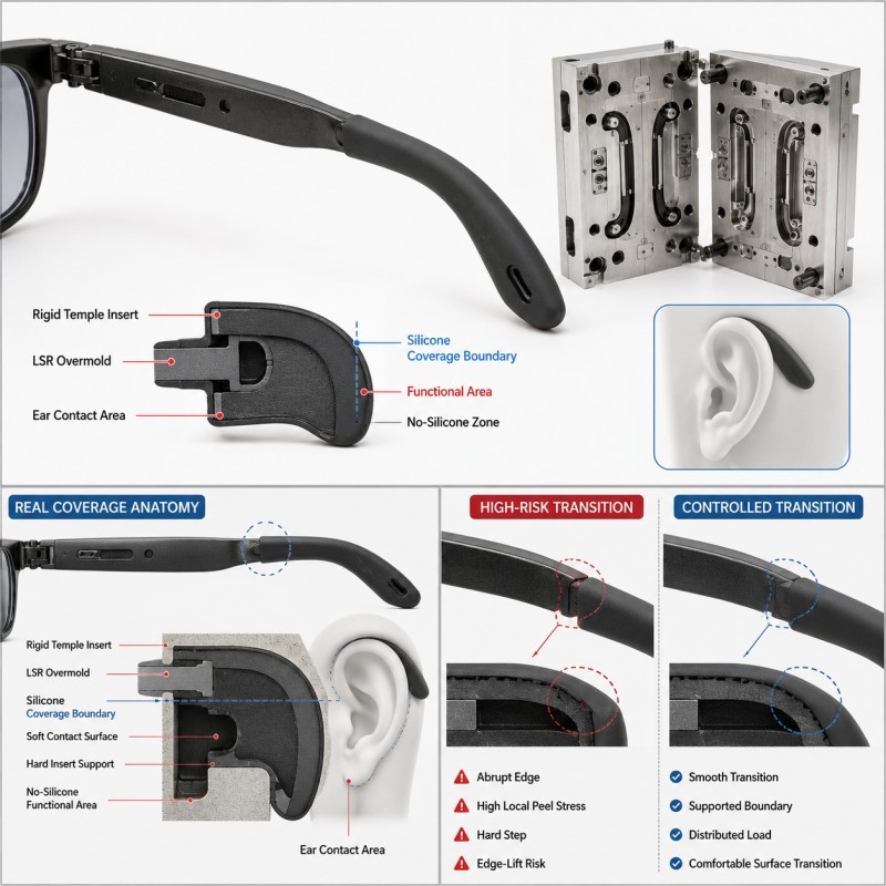
LSR overmolded smart glasses temple tips should provide soft ear contact and anti-slip grip while remaining securely attached to the rigid temple insert. The silicone should cover only the intended wearer-contact area, while hinges, speaker openings, charging contacts, sensors and other functional regions remain exposed. Reliable design requires controlled coverage, suitable hardness and thickness, smooth edge transitions, stable insert positioning, and a validated bonding or mechanical-retention strategy.
Smart glasses temple tips are different from ordinary removable silicone sleeves.
In an overmolded structure, the liquid silicone rubber is molded directly onto a selected area of the plastic or metal temple insert.
This creates an integrated soft-touch section that cannot shift or rotate like a separately assembled sleeve.
However, simply adding more silicone to the rear temple does not automatically improve comfort or retention.
A thick and hard overmold can create pressure behind the ear, while a very thin or poorly retained silicone section may peel, move or tear during repeated wear.
The design therefore needs to balance wearer comfort, anti-slip performance, structural retention and the functional requirements of the smart-glasses electronics.
For an actual product example, review our custom LSR overmolded smart glasses temple tips.
Where Should the Silicone Coverage Start and Stop?
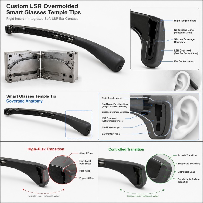
The silicone coverage should follow the real wearer-contact and product-function requirements.
On smart glasses, the rear temple section commonly needs soft-touch and anti-slip performance because it contacts the ear and side of the head.
Other areas may contain mechanical or electronic functions that should remain exposed.
Typical protected areas may include:
• Hinge mechanisms
• Speaker openings
• Charging contacts
• Sensors
• Buttons
• Microphone openings
• Assembly datums
• Decorative or mating surfaces
The coverage boundary should therefore be dimensioned from a stable feature on the temple insert rather than defined only by a product rendering.
A controlled boundary helps prevent three different problems.
First, silicone extending too far forward may interfere with a hinge, speaker or electronic interface.
Second, silicone stopping too early may reduce the intended soft-contact area.
Third, inconsistent boundary position can make left and right temple parts look or feel different.
The DFM drawing should clearly identify the silicone coverage area, the transition boundary and every functional no-silicone zone before tooling.
Why Is the Silicone Edge Transition Important?
The edge where the LSR overmold ends on the rigid temple insert is a critical design region.
This boundary may experience:
• Repeated bending
• Skin and hair contact
• Putting on and removing the glasses
• Cleaning
• Sweat and moisture
• Local peeling force
• Impact during handling
• Repeated friction
A sharp silicone termination can concentrate peel stress at one narrow line.
A very thick termination can create an uncomfortable step against the wearer or make the product look bulky.
A very thin termination may become difficult to fill consistently or may tear during demolding.
Where the product geometry allows it, the silicone should transition smoothly from the main soft-touch section toward the termination edge.
The plastic or metal insert should also provide enough support beneath this region so that repeated bending does not load only the silicone-to-insert boundary.
How Should Silicone Hardness and Thickness Be Balanced?
Wearer comfort depends on the combined stiffness of the silicone material and the molded geometry.
A softer LSR does not automatically produce the most comfortable temple tip.
If the silicone section is very thick, even a relatively soft material can feel bulky or create excessive pressure.
If the section is very thin, a harder material may still flex easily because the geometry provides little resistance.
Important design variables include:
• Silicone hardness
• Wall thickness
• Temple curvature
• Contact length behind the ear
• Local ribs or texture
• Hollow or solid sections
• Plastic insert support
• Transition length
The designer should therefore evaluate hardness and geometry together.
A suitable structure should provide enough cushioning to reduce hard contact with the rigid insert while maintaining enough shape stability for repeated wear.
For a broader material-selection review, see how to choose the right silicone hardness for LSR overmolding.
How Should Anti-Slip Texture Be Designed?
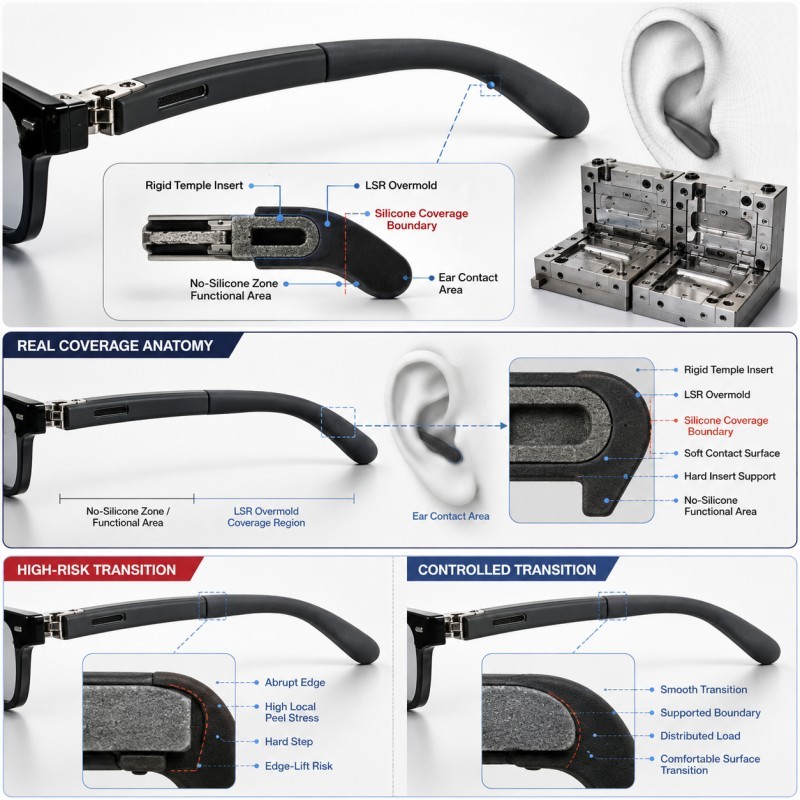
Anti-slip performance can be improved through material friction and controlled surface texture, but the texture should match the real wearer-contact area.
Possible texture strategies include:
• Fine matte texture
• Shallow micro-ribs
• Localized grip zones
• Smooth-to-textured transitions
• Controlled surface roughness
The texture should not create sharp features that become uncomfortable during long wear.
It should also avoid deep grooves that collect dirt, skin oil or cleaning residue unnecessarily.
Texture location matters as much as texture depth.
The highest-friction surface is usually most useful on the area that actually contacts the ear or side of the head.
Adding aggressive texture to a non-contact region increases mold complexity without providing a clear functional benefit.
The texture must also remain compatible with demolding and appearance requirements.
When Does the Temple Tip Need Mechanical Retention?
The rear temple section experiences repeated bending, pulling and friction during normal use.
If the silicone-to-insert interface is exposed to significant peel or sliding load, chemical adhesion alone may not provide the desired design margin.
Mechanical retention may be added to the rigid insert where the real product structure permits it.
Possible retention features include:
• Through-holes
• Slots
• Grooves
• Undercuts
• Edge wraparound
• Local retention windows
The silicone can flow into or around these features and create a physical lock after curing.
However, retention features should not be added blindly.
They must remain compatible with the strength of the temple insert, silicone flow, venting, wall thickness and demolding.
A deep or narrow feature may trap air or create incomplete filling.
A feature positioned too close to a thin temple wall may weaken the insert.
For detailed structure guidance, review when LSR overmolding needs mechanical retention.
Why Does Temple Insert Positioning Matter?
The rigid temple insert must remain in a repeatable position during LSR injection.
If the insert shifts, tilts or lifts inside the mold, the final soft-touch section may change in:
• Silicone thickness
• Coverage length
• Left-to-right symmetry
• Edge position
• Mechanical-lock filling
• Surface appearance
• Final temple dimensions
This is particularly important for smart glasses because the two sides of the product are visually and ergonomically related.
A small variation in the rear temple thickness may change how one side contacts the wearer.
Stable locating features should therefore use rigid and repeatable insert datums.
The mold should also support the insert near the overmolding region so that silicone flow does not push a thin temple structure away from its intended position.
Smart Glasses Temple Tip DFM Checklist
DFM Item | What Engineers Should Confirm | Main Risk |
Coverage area | Rear wearer-contact area is clearly defined | Silicone covers functional areas |
Functional zones | Hinges, speakers, contacts and sensors remain exposed | Product function interference |
Edge transition | Silicone termination is supported and controlled | Peeling or uncomfortable step |
Silicone hardness | Material is reviewed with geometry | Too soft or too rigid |
Wall thickness | Contact area remains comfortable and moldable | Bulky feel or tearing |
Surface texture | Grip is added only where useful | Discomfort or dirt retention |
Insert strength | Rigid temple supports the soft overmold | Local deformation |
| Mechanical retention | Lock features match real load direction | Peel or sliding failure |
| Insert positioning | Temple remains repeatable in the mold | Uneven left/right geometry |
| Shut-off | Functional areas remain protected | Flash or silicone intrusion |
| Validation | Wear, pull, bend and appearance tests are defined | Sample looks good but use fails |
The silicone mold design and tooling review should confirm the temple insert datum, silicone coverage boundary, edge transition, retention features, mold shut-off, gate, venting and demolding direction before mold steel is finalized.
How Should Smart Glasses Temple Tips Be Validated?
Smart glasses temple tips should be validated on the final eyewear assembly rather than only as isolated overmolded inserts.
Recommended validation includes:
1. Silicone Coverage Inspection
Confirm that the rear soft-touch area matches the approved drawing and that functional electronic areas remain exposed.
2. Dimensional Inspection
Measure critical temple thickness, silicone boundary, left-right symmetry and final assembly dimensions.
3. Pull and Peel Review
Where appropriate, evaluate whether repeated handling can lift the silicone from the rigid temple insert.
4. Bend and Flex Testing
Repeat the expected temple movement and check the silicone termination and retention areas for cracking, lifting or permanent deformation.
5. Wearing-Fit Evaluation
Confirm that the rear temple provides stable contact without excessive local pressure or slipping.
6. Surface and Appearance Inspection
Check texture consistency, flash, contamination, visible boundary quality and cosmetic symmetry.
7. Sweat and Cleaning Exposure
Where required by the product specification, repeat functional inspection after the defined moisture, sweat-simulation or cleaning conditions.
8. Pilot-Production Validation
Compare multiple mold cavities and consecutive production cycles before mass-production approval.
The final approval should confirm both manufacturing repeatability and wearer-contact performance.
How SiliconePlus Supports Smart Glasses Silicone Overmolding
SiliconePlus supports custom smart glasses and wearable-device LSR overmolding projects from product and insert review through tooling, sampling, inspection and mass production.
Project support can include:
• Smart glasses temple insert DFM
• Silicone coverage definition
• Functional no-silicone-zone review
• Hardness and wall-thickness evaluation
• Edge-transition design review
• Mechanical-retention design
• Insert-positioning and support review
• Mold shut-off analysis
• Gate and venting review
• Precision mold development
• LSR injection molding
• Dimensional and appearance inspection
• Pull, bend and pilot-production validation
Specific silicone coverage, hardness, surface texture, retention and acceptance criteria should always be confirmed according to the actual eyewear structure, wearer-contact area and customer test requirements.
FAQ
Should the Entire Smart Glasses Temple Be Covered with Silicone?
No. Silicone should normally cover only the intended soft-touch and wearer-contact area. Hinges, speakers, charging contacts, sensors and other functional regions should remain exposed according to the product design.
Is Softer Silicone Always More Comfortable?
No. Comfort depends on both hardness and geometry. A very thick soft overmold can still create pressure or bulk.
Can the Silicone Temple Tip Be Made as a Separate Sleeve Instead?
A separate sleeve is possible in some products, but LSR overmolding creates an integrated structure that can improve positioning and reduce sleeve movement. The correct solution depends on the product architecture.
Does the Silicone Need Mechanical Retention?
Not every project requires it. Mechanical retention is more useful when the interface experiences significant peeling, bending, pulling or sliding loads.
Can Anti-Slip Texture Be Added Everywhere?
It can be molded into selected areas, but texture should be concentrated where it provides a real grip benefit and should remain comfortable and cleanable.
Should Smart Glasses Temple Tips Be Tested Only for Appearance?
No. Final validation should also consider coverage, dimensional repeatability, bonding or retention, bending, fit and the actual wearing environment.
Conclusion
A reliable LSR overmolded smart glasses temple tip is not created by simply making the rear temple softer.
The design must coordinate:
• Silicone coverage
• Functional exposed areas
• Edge transition
• Silicone hardness
• Wall thickness
• Surface texture
• Insert support
• Mechanical retention
• Insert positioning
• Wear and flex validation
The best design keeps the silicone only where it improves wearer contact while protecting the electronic and mechanical functions of the smart glasses.
These requirements should be reviewed during DFM before tooling, when the silicone boundary, insert structure and retention features are still practical to change.
Developing a Custom Smart Glasses Silicone Component?
If you are developing AI glasses, AR eyewear or another wearable device with LSR overmolded temple tips, send your temple insert drawing, substrate material, silicone coverage area, hardness requirement and expected quantity to the SiliconePlus engineering team for a project-specific review.