How Do You Protect FPC Gold Fingers and Contact Pads During LSR Overmolding?
- Share
- publisher
- siliconeplus
- Issue Time
- Jul 29,2026
Summary
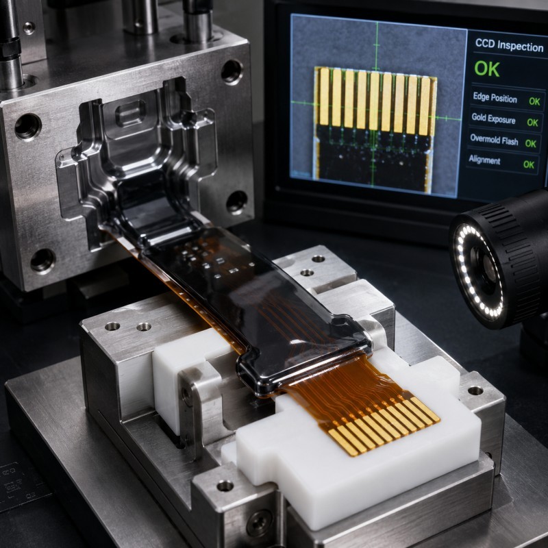
FPC gold fingers and contact pads must remain clean, exposed and dimensionally stable during LSR overmolding. Protection depends on a clearly defined no-silicone zone, accurate FPC positioning, flat support, controlled mold shut-off, suitable gate direction and repeatable inspection. Engineers should validate pad exposure through CCD inspection, dimensional measurement, electrical testing and connector assembly before mass production.
Answer Excerpt
FPC gold fingers and contact pads should be protected by defining an exact no-silicone zone, supporting the flexible circuit inside the mold, controlling its position, and creating a precise mold shut-off around the exposed area. Gate direction, injection pressure, parting-line location and FPC tolerance must also be reviewed. Protection should be verified through optical inspection, dimensional measurement, electrical testing, connector assembly and pilot production before mass production.
FPC silicone overmolding can integrate waterproof sealing, electrical insulation, strain relief and mechanical protection into a compact electronic component.
However, silicone cannot cover every part of the flexible circuit.
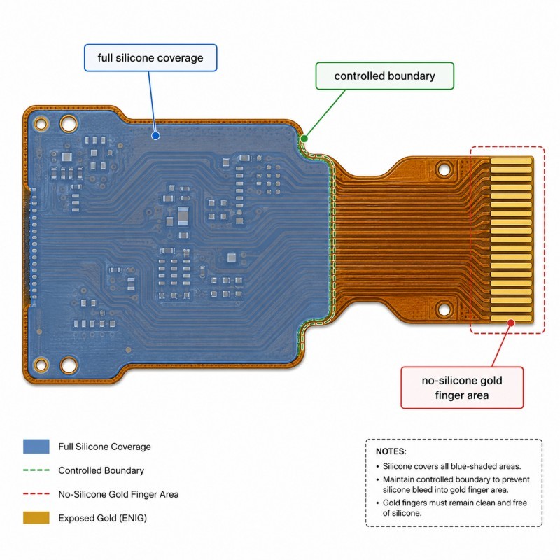
Some FPC areas require full silicone encapsulation, while gold fingers, contact pads, test points, grounding areas and connector interfaces must remain completely exposed.
A thin transparent silicone film may be difficult to see, but it can still prevent stable electrical contact or interfere with connector insertion. Functional-area protection must therefore be treated as a critical mold-design and production-control requirement.
For projects involving flexible circuits, sensors and compact waterproof electronics, FPC with silicone overmolding manufacturing should be reviewed before tooling begins.
Which FPC Areas Must Remain Exposed?
The areas that must remain exposed are determined by the electrical, mechanical and assembly functions of the final product.
Typical no-silicone areas include:
• Gold fingers
• Contact pads
• Connector fingers
• Test points
• Grounding pads
• Charging contacts
• Soldering pads
• Optical sensor windows
• Component contact surfaces
• ZIF connector insertion areas
• Required bending zones
• Assembly reference holes
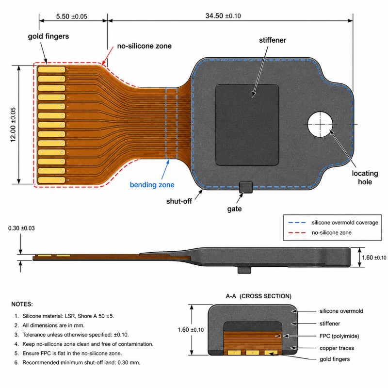
The engineering drawing should distinguish three different areas:
1. Full silicone coverage zone
2. Controlled silicone boundary zone
3. Completely exposed no-silicone zone
A colored product rendering alone is not sufficient.
The drawing should define the exact silicone boundary relative to stable FPC datums, locating holes, stiffeners, contact pads and connector insertion dimensions.
The required exposed pad length, silicone boundary tolerance and acceptable flash limit should all be confirmed before mold manufacturing.
What Failure Symptoms Appear When Contact Pads Are Not Protected?
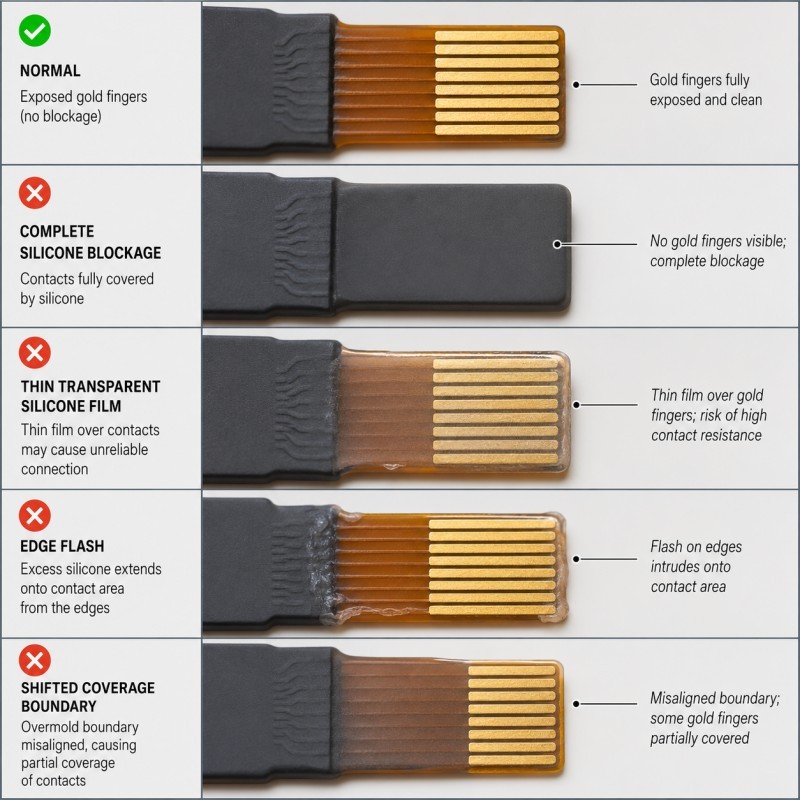
The most common symptoms are blocked contacts, silicone flash, unstable pad exposure and intermittent electrical connection.
Silicone Fully Covers the Contact Pad
This is the most obvious failure. The connector cannot establish electrical contact because silicone forms an insulating layer over the conductive area.
A Thin Silicone Membrane Remains on the Pad
This defect is more difficult to detect. The pad may appear exposed under ordinary lighting, but a transparent silicone film remains on the surface.
Possible consequences include:
• High contact resistance
• Intermittent signal transmission
• Failed electrical testing
• Unstable charging
• Connector insertion difficulty
• Field failure after repeated assembly
The Silicone Coverage Boundary Shifts
The silicone may stop too early on one sample and extend too far on another. This normally indicates unstable FPC positioning, deformation or mold shut-off.
Flash Forms Around the Gold-Finger Edge
Flash may interfere with ZIF connector insertion, spring-contact pressure, connector alignment and assembly depth.
The FPC Is Scratched or Indented
The mold may successfully stop silicone but mechanically damage the plated pad, copper trace, coverlay or stiffener.
The Sample Passes but Mass Production Fails
Initial samples may be carefully loaded by engineers, while mass production introduces variation in FPC position, operator handling, insert flatness, mold wear and cycle conditions.
Related problems involving holes, contact pads and connector openings should also be evaluated during DFM.
Why Does Silicone Enter the Gold-Finger Area?
Silicone enters the protected area when a gap develops between the FPC and the mold shut-off.
Liquid silicone must flow into thin sealing structures and complex cavities. The same low-viscosity flow behavior means it can also enter small uncontrolled gaps around a flexible insert.
The main causes include:
• FPC position shift
• FPC bowing or lifting
• Incorrect locating-hole tolerance
• Uneven stiffener thickness
• Insufficient flat support
• Mold shut-off mismatch
• Parting line crossing the contact pad
• Excessive local injection pressure
• Gate flow pushing the FPC
• Contamination on the shut-off
• Mold wear
• FPC thickness variation
• Incorrect loading direction
The exact cause should be confirmed by inspecting the silicone boundary, FPC position, mold contact marks and defect direction.
1. The No-Silicone Zone Is Not Clearly Defined
The first requirement is an unambiguous silicone coverage drawing.
A drawing that only states “do not cover the contact area” does not provide enough information for precision tooling.
The drawing should define:
• Contact-pad width and length
• Required exposed length
• Silicone boundary position
• Boundary tolerance
• Distance from the silicone edge to the active pad
• Allowed flash limit
• FPC datum
• Locating-hole position
• Stiffener position
• Connector insertion depth
The no-silicone zone should be dimensioned from stable FPC datums rather than from an irregular outer edge.
Different colors or hatch patterns can be used to identify full coverage, controlled coverage and completely exposed areas.
Title
FPC is thin, light and flexible, so small handling or pressure changes can move the silicone boundary.
Possible movement modes include sliding, rotation, bowing, wrinkling, lifting and twisting.
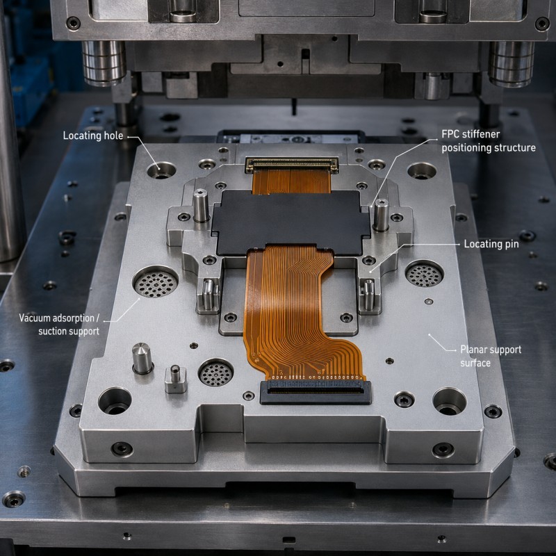
Positioning methods may include:
• Precision locating holes
• Datum edges
• Stiffener positioning
• Vacuum holding
• Flat support plates
• Controlled clamping
• Guide pins
• Camera-assisted loading
• Robotic insert loading
• Temporary carrier frames
The positioning method should be located close to the protected contact area.
Locating pins must not stretch or pull the FPC into an unnatural position. Otherwise, the circuit may appear flat in the mold but retain stress after demolding.
3. The FPC Does Not Have Enough Flat Support
A flexible circuit cannot maintain a precise silicone boundary if the mold supports it only at a few distant points.
When injection pressure reaches an unsupported area, the FPC may lift away from the mold surface and create a gap.
Flat support should be evaluated around:
• Gold fingers
• Contact-pad edges
• Thin FPC tails
• Test points
• Stiffener edges
• Component transitions
• Bending zones
• Connector interfaces
Support should be close enough to prevent movement but must not crush circuits, components or plated surfaces.
For an FPC containing electronic components, the mold may require component-clearance cavities while still supporting the circuit around the no-silicone boundary.
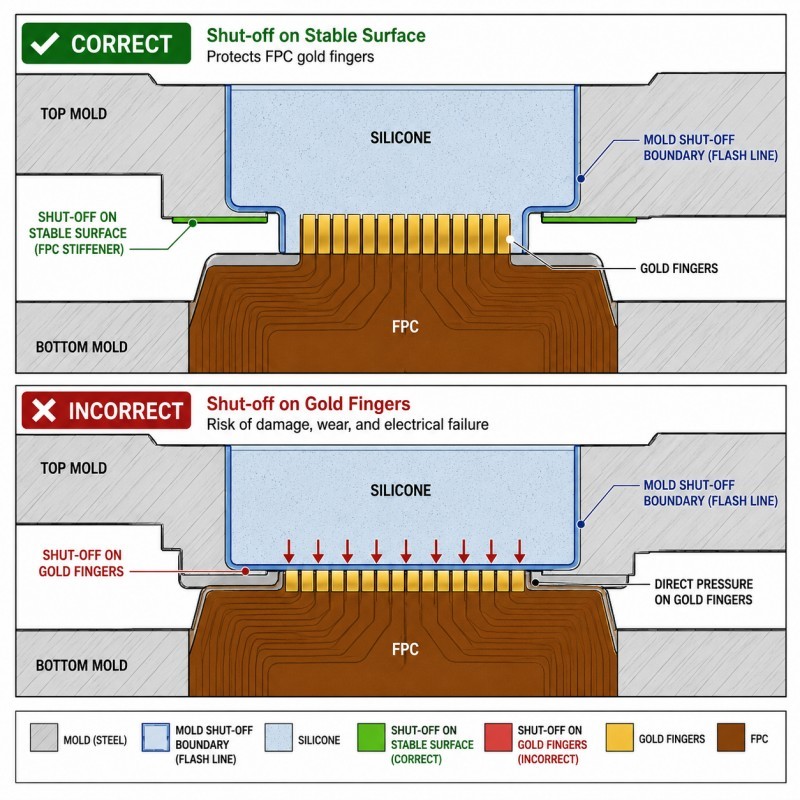
4. The Mold Shut-Off Is Not Located on a Stable Surface
The mold shut-off is the contact boundary where the mold prevents uncured silicone from entering the protected area.
If the shut-off is too narrow or located across an unstable thickness transition, silicone flash may appear.
High-risk shut-off locations include:
• Stiffener edges
• Coverlay steps
• Uneven adhesive layers
• Component boundaries
• Curved FPC regions
• Creased areas
• Irregular trimmed edges
• Damaged plated surfaces
A suitable shut-off should contact a flat and repeatable region, have sufficient sealing width and tolerate expected FPC thickness variation.
Where possible, the mold should shut off on the coverlay or a dedicated border around the contact area instead of pressing directly on the active gold fingers.
5. Gate Direction Pushes the FPC Toward the Protected Area
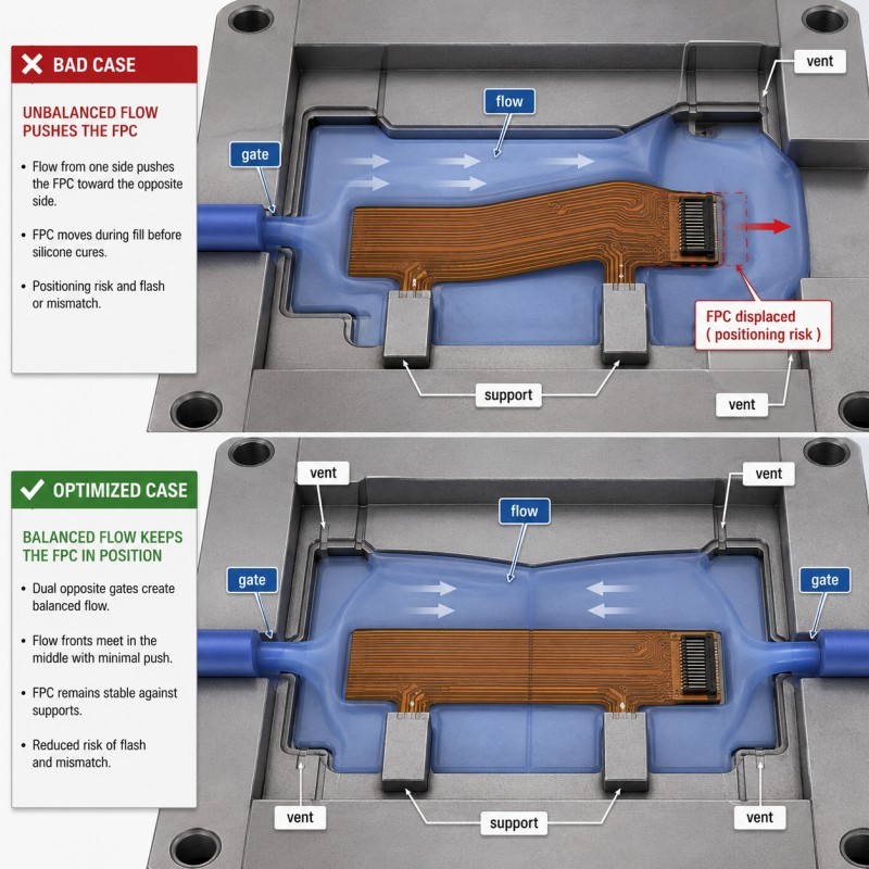
The gate should fill the silicone region without lifting, shifting or twisting the FPC.
If the initial flow front hits the FPC edge directly, the circuit may move before the cavity pressure becomes balanced.
Possible consequences include:
• Pad-coverage shift
• Uneven silicone thickness
• FPC bowing
• Local flash
• Weld lines
• Trapped air
• Electronic-component stress
Gate review should consider the initial flow direction, distance from the FPC edge, pressure balance, final fill position, vent location and mechanical support near the gate.
The objective is a repeatable process window that fully forms the silicone structure without moving the flexible circuit.
What Is the Recommended Gold-Finger Protection Structure?
A reliable structure combines a clearly defined no-silicone zone, stable FPC positioning, flat support and a precise mold shut-off.
Stable FPC Datum
The FPC should have repeatable locating features positioned close to the protected area.
Flat Support Beneath the Contact Area
The support prevents injection pressure from lifting the FPC and opening a silicone leakage gap.
Dedicated Mold Shut-Off Border
The mold should seal around the no-silicone zone without depending on an irregular FPC outer profile.
Sufficient Distance from Active Contacts
The silicone boundary should not terminate directly on the active mating edge unless the product structure specifically requires it.
Controlled Transition into the Overmolded Area
A smooth transition reduces local stress and helps keep the flexible circuit flat during molding and demolding.
Protection from the Parting Line and Gate
The pad area should be separated from high-risk flow, flash and mold-wear locations.
A custom FPC silicone overmolded waterproof seal should define exposed terminals, positioning-hole clearance, silicone boundaries and inspection requirements before tooling.
DFM Checklist Before FPC Overmolding Tooling
| DFM Item | What Engineers Should Confirm |
FPC stack-up | Base film, copper, adhesive, coverlay and stiffener are defined |
Gold-finger location | Pad position is controlled from stable datums |
No-silicone zone | Completely exposed areas are clearly marked |
Coverage boundary | Silicone termination and tolerance are defined |
FPC positioning | Locating holes, edges or stiffeners provide repeatable positioning |
Flat support | The FPC cannot lift under injection pressure |
Pad protection | Mold shut-off does not damage the plated surface |
Parting line | It does not cross critical contact areas |
Gate position | Flow does not push or distort the FPC |
| Component clearance | The mold does not crush electronic components |
| Stiffener tolerance | Thickness and position are included in shut-off design |
| Inspection | Gold fingers can be inspected optically and electrically |
The silicone mold design and tooling review should be completed together with the FPC drawing, complete assembly, coverage map and electrical test requirements.
How Should Protected Gold Fingers Be Inspected?
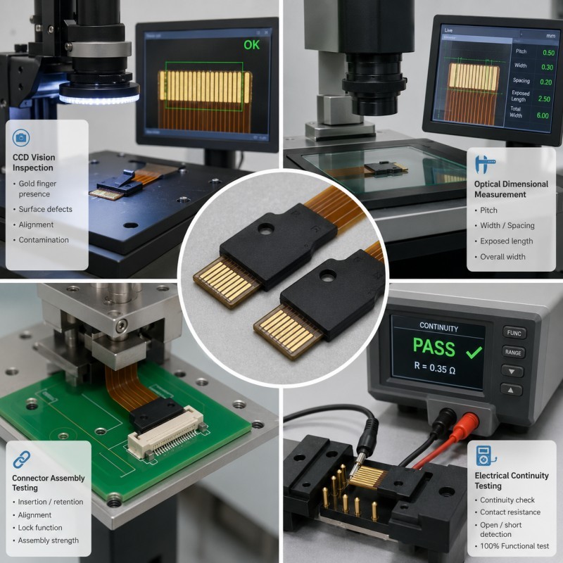
Protected gold fingers should be inspected visually, dimensionally, electrically and through actual connector assembly.
1. CCD or Optical Inspection
CCD inspection can identify silicone on the pad, boundary shift, flash, pad scratches, incorrect orientation and surface contamination.
Controlled lighting is important because a thin transparent silicone film may not be visible under ordinary lighting.
2. Dimensional Measurement
Measure the exposed pad length, silicone-to-pad distance, silicone-boundary position, FPC location and connector insertion area.
Optical measuring equipment is normally more suitable than contact measurement for small flexible structures.
3. Electrical Continuity Testing
Continuity testing confirms that the intended circuit path remains connected after molding.
However, continuity alone may not identify every contact-surface problem.
4. Contact-Resistance or Functional Testing
Where required, evaluate contact resistance, signal stability, charging performance, sensor response, communication function or grounding performance.
5. Connector Insertion Testing
Insert the FPC into the actual ZIF or mating connector and verify insertion depth, locking, alignment and contact stability.
6. Cross-Section Inspection
Cross-section analysis can evaluate the silicone boundary, FPC flatness, voids, layer deformation and local silicone thickness.
7. Environmental Validation
Depending on the application, repeat inspection after thermal cycling, humidity exposure, water immersion, repeated bending, vibration or connector mating cycles.
8. Pilot-Production Validation
Do not approve the project based only on one good sample. A pilot run should confirm consecutive-cycle positioning, operator-loading consistency, flash stability and electrical pass rate.
Common Failure Symptoms and Corrective Actions
| Failure Symptom | Likely Cause | Recommended Action |
Entire pad is covered | Incorrect loading or failed shut-off | Improve positioning and orientation control |
Transparent film remains | Small shut-off gap | Improve flat support and mold contact |
Flash appears on one side | FPC tilt or uneven thickness | Check support, stiffener and flatness |
Exposure length changes | Positioning variation | Move the datum closer to the pad |
| Pad is scratched | Excessive mold contact | Move shut-off away from the active pad |
| FPC creases near silicone edge | Poor support or demolding stress | Improve transition and support |
| Connector cannot lock | Flash or insufficient exposed length | Increase controlled clearance |
Samples pass but production fails | Loading variation or mold wear | Add camera control and maintenance limits |
Typical Applications
FPC contact protection is especially important in compact products that combine electrical contacts with waterproof or soft silicone structures.
Wearable Electronics
• Smartwatch sensor modules
• Fitness trackers
• Health-monitoring patches
• Charging-contact modules
• Skin-contact sensors
Automotive Electronics
• FPC sensor modules
• Battery electronic modules
• Connector seals
• Steering-wheel controls
• Flexible lighting modules
Medical and Healthcare Devices
• Wearable monitoring sensors
• Diagnostic-device modules
• Respiratory-device electronics
• Portable medical devices
Consumer Electronics
• Waterproof buttons
• Camera modules
• Charging interfaces
• Earphone components
• Compact sensor assemblies
Industrial Equipment
• Flexible sensor circuits
• Waterproof control interfaces
• Robotics modules
• Outdoor instruments
• Compact connector systems
How SiliconePlus Supports FPC Overmolding Projects
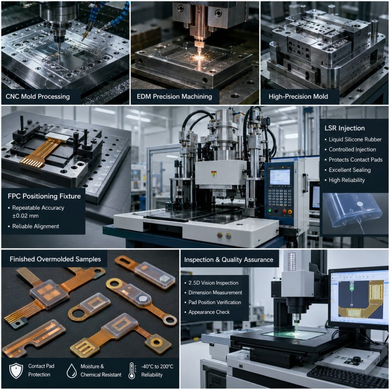
SiliconePlus supports FPC overmolding projects from coverage-boundary review through tooling, sampling, inspection and mass production.
Project support can include:
• FPC drawing and stack-up review
• Gold-finger and contact-pad protection analysis
• Silicone coverage-map review
• FPC positioning method development
• Stiffener and locating-hole review
• Mold shut-off design
• Gate and venting review
• Component-clearance design
• FPC support-fixture development
• LSR injection molding
• CCD and dimensional inspection
• Electrical test coordination
• Waterproof test support
• Prototype and pilot production
• OEM and ODM mass production
SiliconePlus has 25 years of silicone manufacturing experience, more than 6,000 developed silicone projects, in-house CNC and EDM mold-processing capability, liquid silicone injection equipment and precision measuring resources.
Specific tolerances, waterproof performance and electrical acceptance standards should be confirmed according to the actual FPC structure, material combination, assembly and agreed test method.
FAQ
Can LSR Be Molded Directly Over an FPC?
Yes. LSR can be molded onto selected FPC areas for sealing, insulation, strain relief and mechanical protection. Pad exposure, component temperature resistance, positioning and mold shut-off must be reviewed first.
Can Silicone Cover the Gold Fingers?
No, not when the gold fingers need to mate with a connector or electrical contact. The active contact area must remain completely exposed and clean.
How Can Transparent Silicone Film on a Pad Be Detected?
Use controlled lighting, CCD inspection, magnification and electrical or connector-function testing. Ordinary visual inspection may not detect a very thin transparent film.
Should the Mold Press Directly on the Gold Fingers?
Direct pressure on an active plated surface should be avoided where possible. A dedicated coverlay border or stable support region is normally safer.
Why Does the FPC Move During LSR Injection?
The FPC may move because it is thin, unsupported, incorrectly located or directly exposed to gate-flow pressure.
Can Manual Trimming Remove Silicone from the Pads?
Manual trimming is not recommended as the primary control method. It can leave thin silicone film, scratch the pad or create inconsistent exposure dimensions.
Is CCD Inspection Enough?
No. CCD inspection is valuable, but electrical testing and actual connector assembly may also be required.
What Files Are Needed for FPC Overmolding DFM?
Provide the FPC 2D drawing, stack-up, 3D assembly, component heights, stiffener information, contact-pad dimensions, silicone coverage area, bending requirements, waterproof target and electrical test criteria.
Conclusion
Protecting FPC gold fingers and contact pads during LSR overmolding requires coordinated control of:
• No-silicone-zone definition
• FPC positioning
• Flat support
• Mold shut-off
• FPC thickness tolerance
• Stiffener location
• Parting-line position
• Gate direction
• Injection pressure
• Mold maintenance
• Optical inspection
• Electrical validation
The best time to solve these risks is during DFM, before the mold is manufactured.
For a project-specific evaluation, send your FPC drawing, stack-up, silicone coverage map and electrical requirements to the SiliconePlus engineering team.