How Can LSR Overmolding Seal ADAS Camera Housings Without Disturbing Lens Alignment?
- Share
- publisher
- SiliconePlus Engineering Team
- Issue Time
- Oct 13,2026
Summary
ADAS camera housing seals must protect against moisture and dust without introducing uncontrolled assembly forces near optical alignment features. This guide explains how LSR overmolding, seal compression, rigid housing datums, mounting tolerances and vibration validation should be coordinated for custom automotive camera modules.
Answer Excerpt
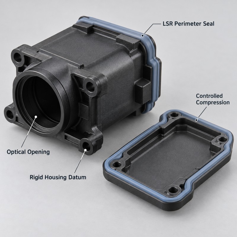
An LSR overmolded ADAS camera housing seal should provide the required environmental sealing without introducing uncontrolled deformation into the rigid features that position the optical assembly.
The sealing function and optical alignment function should be designed together, but they do not necessarily use the same mechanical reference surfaces.
A reliable design should consider:
• Continuous silicone sealing geometry
• Rigid optical locating datums
• Lens-opening clearance
• Seal compression and reaction force
• Housing and cover stiffness
• Mounting-screw position
• Plastic insert tolerance
• Assembly gap variation
• Vibration and temperature exposure
• Dimensional and environmental validation
The objective is not simply to make the camera housing waterproof.
The objective is to maintain the specified sealing condition while preserving the mechanical geometry required by the customer's camera module.
SiliconePlus manufactures the custom LSR sealing and overmolded housing components. Final camera calibration, optical performance and complete ADAS system validation must be confirmed by the customer.
Why Can Camera Housing Sealing Affect Optical Alignment?
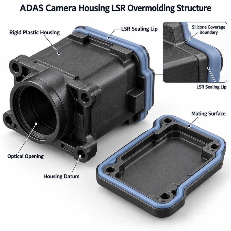
An automotive camera module contains several structures that must work together after final assembly.
Depending on the design, these may include:
• Lens or optical module
• Rigid camera housing
• Lens support or locating features
• Housing cover
• Perimeter sealing structure
• Fasteners and mounting supports
• Electrical connector
• Vehicle mounting interface
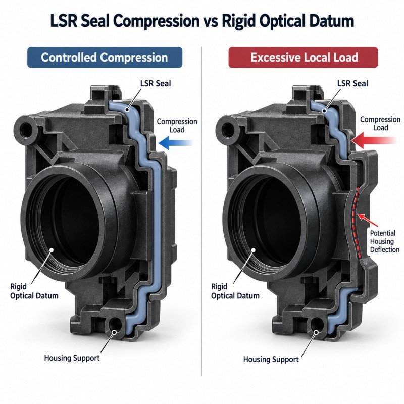
When the camera housing is assembled, the silicone seal is compressed between its mating surfaces.
The compressed silicone generates a reaction force.
If the surrounding housing is insufficiently rigid, or if the fastener arrangement produces uneven closure, the assembly may deform locally.
Where optical components share that load path, the deformation may influence their mechanical position.
This does not mean every silicone seal causes lens misalignment. The effect depends on housing design, seal geometry, stiffness, assembly tolerances and how the optical components are located.
The correct engineering approach is to establish the optical locating system and evaluate how the sealing system interacts with it.
1.Separate the Sealing Path From the Optical Locating Datums
One of the first DFM questions is:
Which rigid surfaces determine the position of the camera's optical components?
These surfaces may include shoulders, support seats, locating faces or customer-defined mechanical datums.
The LSR sealing feature should be positioned so that normal compression does not unintentionally change the required relationships between these locating surfaces.
For automotive silicone overmolding projects, the design review should distinguish:
• Optical locating surfaces
• Silicone sealing contact areas
• Fastener clamping regions
• Plastic housing support features
• Mating-cover surfaces
• Functional openings
• Inspection datums
An elastomeric sealing lip should not be treated as a precise optical locating feature unless that function has been intentionally designed and validated.
If the sealing structure is close to a rigid optical reference, engineers should review whether its compression load can bend or tilt the supporting plastic.
The assembly should maintain the necessary rigid locating geometry at the minimum, nominal and maximum intended seal compression conditions.
2.Control Silicone Compression Without Overloading the Camera Housing
A silicone over plastic structure can integrate the sealing lip directly onto a heat-resistant plastic camera housing.
This can help keep the gasket in its intended position during handling and assembly.
However, integrated construction does not eliminate the need for compression control.
The final sealing condition depends on:
• Free silicone seal height
• Seal contact width
• Silicone hardness
• Mating-cover geometry
• Assembly closing gap
• Housing stiffness
• Fastener spacing
• Local cover flatness
• Rigid compression stops, where applicable
• Dimensional tolerances
Insufficient compression may leave an environmental leakage path.
Excessive compression may increase assembly load, distort the seal or apply unwanted force to the rigid housing.
The correct range must be established from the actual product and sealing requirement rather than applying one universal compression percentage.
For sensitive camera structures, the mechanical design should ensure that the assembled position is controlled primarily by appropriate rigid features.
The silicone should provide the required flexible contact without becoming an uncontrolled spacer that changes the optical assembly position.
3.Review Fastener Layout and Housing Stiffness Together
A camera housing cover may be held by screws, clips or another customer-defined fastening structure.
The location and stiffness of these features influence how the assembly closes around a perimeter seal.
A cover that is supported strongly near a fastener but less strongly between fasteners may not compress the seal uniformly.
Potential risks include:
• Lower compression between fasteners
• Local over-compression near rigid supports
• Housing-cover bending
• Uneven sealing-lip contact
• Changes in assembly gap
• Local movement near optical locating surfaces
Engineers should evaluate the full housing rather than only the nominal silicone cross-section.
A useful review may compare the planned assembly under different dimensional and fastening conditions.
Where the structure requires highly controlled geometry, the customer may also evaluate deformation using an appropriate structural analysis or representative physical assembly testing.
The molding supplier should provide realistic silicone geometry, hardness and dimensional information for that evaluation.
A perfectly molded silicone seal cannot compensate for an unsuitable housing or fastener arrangement.
4.Control Plastic Housing Position During LSR Overmolding
The camera housing must remain stable inside the mold while liquid silicone is introduced around the selected sealing region.
If the rigid insert is tilted or not fully seated, the final silicone geometry may shift relative to the housing datums.
This is especially important when the seal must mate accurately with a separate cover.
During DFM, insert positioning should be reviewed in relation to:
• Rigid housing locating surfaces
• Insert flatness and warpage
• Silicone cavity location
• Gate and flow direction
• Mold shut-off boundaries
• Optical keep-out areas
• Final sealing-lip dimensions
• Inspection reference points
A position error may create a seal that is higher on one side and lower on another.
The resulting assembly could show uneven compression even though the silicone material itself is acceptable.
Incoming plastic housing variation should also be considered.
A repeatable mold cannot fully eliminate variation introduced by unstable insert dimensions.
Critical dimensions should be inspected relative to functional datums on the rigid housing, not only relative to the exterior silicone appearance.
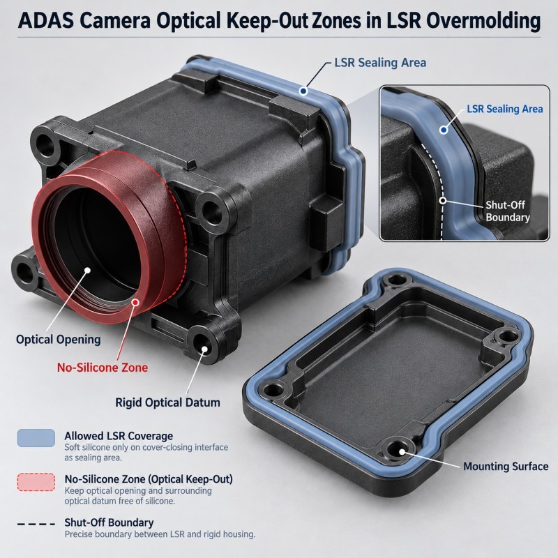
5.Keep the Lens Opening and Optical Reference Surfaces Free From Silicone
The silicone coverage boundary must protect all areas that need to remain exposed.
Depending on the camera structure, these may include:
• Lens opening
• Optical window
• Lens support face
• Calibration reference surfaces
• Electrical connector
• Mounting holes
• Fastener seats
• Housing datums
• Required heat-transfer surfaces
These areas should be clearly identified before tooling.
The silicone should form a continuous seal around the intended housing interface without entering the optical opening or coating the required reference surfaces.
A thin silicone film may interfere with optical assembly, inspection or final module fit even when it appears visually minor.
Mold shut-off design should therefore provide a controlled transition between the silicone-covered region and the exposed rigid housing.
It is also important to define which surfaces are permitted to have minor cosmetic flash and which must remain completely free of silicone.
Manual trimming around an optical reference should not be relied upon as the primary production control method.
The correct design protects the functional area during molding rather than attempting to recover it afterward.
6.Validate Sealing Loads Under Vibration and Thermal Cycling
Automotive cameras may experience vibration, temperature changes, humidity and environmental exposure during service.
These conditions can change the relationship between the rigid housing, the silicone seal and the mating cover.
Potential effects include:
• Housing expansion or contraction
• Changes in sealing compression
• Local seal movement
• Interface edge lifting
• Fastener-related deformation
• Plastic creep or warpage
• Changes in assembly fit
• Leakage after environmental cycling
The actual material combination determines the level of risk.
Silicone and engineering plastics do not necessarily expand, deform or recover in the same way.
Therefore, a seal that provides sufficient contact at room temperature should also be reviewed under the project's required operating conditions.
The validation plan should distinguish:
• Environmental sealing performance
• Mechanical housing deformation
• Functional optical alignment
• Electrical interface condition
A successful waterproof test alone does not establish that camera calibration or imaging performance remains within specification.
The customer should confirm those functions on the complete camera module after the appropriate environmental and mechanical testing.
7.Material Selection and Molding Process Must Match the Housing Design
The rigid housing material must be suitable for the selected LSR injection molding process.
During material and tooling review, important considerations include:
• Plastic material grade
• Heat resistance
• Dimensional stability
• Surface condition
• Silicone adhesion requirements
• Mold temperature
• Insert support
• Silicone hardness
• Sealing-lip geometry
• Demolding direction
The plastic name alone is not enough to confirm suitability.
Different grades within the same polymer family may respond differently to molding temperature, surface treatment and silicone bonding.
Some designs may rely on an appropriate self-bonding LSR grade.
Others may require a validated surface treatment, primer system or mechanical retention feature.
No particular bonding method should be assumed before the real substrate, silicone grade and functional loading conditions are reviewed.
For automotive camera housings, the selected process must reproduce the intended silicone coverage without distorting the critical rigid structure.
The final material combination should be validated using representative production samples.
How Should an ADAS Camera Housing Seal Be Validated?
Validation should be based on the complete mechanical assembly and the customer's intended operating requirements.
For the overmolded component, a practical review may include:
• Incoming plastic housing inspection
• Silicone coverage inspection
• Seal height and width measurement
• Mold flash inspection
• Optical opening clearance inspection
• Housing datum measurement
• Silicone adhesion or retention evaluation
• Assembly-fit verification
• Sealing compression assessment
• Pilot-production repeatability
For the complete camera assembly, customer-defined testing may include:
• Air-leak or waterproof testing
• Dust ingress testing
• Temperature cycling
• Vibration testing
• Housing deformation measurement
• Lens or optical alignment verification
• Camera calibration checks
• Functional performance testing after environmental exposure
The test sequence should be agreed before tooling and sample approval.
A component should not be described as IP67, IP68 or qualified for an ADAS application solely because it contains a molded LSR seal.
The applicable environmental performance and optical function must be verified on the final assembly according to the project's specified conditions and acceptance criteria.
| Engineering Item | Main Risk | Design Control | Validation Focus |
Optical datum | Housing load changes lens position | Rigid locating features | Datum measurement |
Silicone compression | Too much or too little contact | Seal geometry and assembly gap | Compression verification |
Fastener layout | Uneven housing closure | Cover stiffness and mounting arrangement | Assembly deformation |
Insert positioning | Seal shifts relative to housing | Stable mold locating surfaces | Dimensional inspection |
Lens opening | Silicone contaminates optical area | Mold shut-off and keep-out zones | Optical opening inspection |
Plastic material | Distortion during molding | Grade and process compatibility | Incoming and post-mold checks |
Silicone interface | Edge lifting or separation | Validated bonding or retention | Interface testing |
| Thermal cycling | Changes in seal or housing geometry | Material and tolerance review | Environmental testing |
| Vibration | Movement or fatigue at interfaces | Assembly support and seal design | Customer-defined vibration test |
| Camera performance | Optical function changes after assembly | Complete mechanical validation | Customer optical test |
When Is Integrated LSR Overmolding Suitable for Automotive Camera Housings?
An integrated silicone sealing structure may be suitable when a camera housing requires a continuous, repeatable gasket position along a defined interface.
Potential applications include:
• Front-view ADAS camera housings
• Surround-view camera housings
• Rear-view camera modules
• Parking-assistance camera assemblies
• Exterior automotive camera housings
• Selected vehicle monitoring camera interfaces
Compared with a separate loose gasket, an integrated overmolded seal may reduce gasket handling and help maintain a consistent sealing position.
However, the decision should be made after reviewing the rigid housing, optical locating system, required compression and assembly method.
SiliconePlus offers a custom LSR overmolded automotive camera module housing seal for customer-defined plastic camera housings, with local silicone sealing or cushioning structures while preserving the required optical and assembly areas.
The manufacturing scope covers the custom silicone component and overmolding process, not the complete camera, optical module or vehicle ADAS system.
What Should Be Included in an ADAS Camera Seal RFQ?
For a custom automotive camera housing seal project, useful engineering information includes:
• 2D camera housing drawing
• 3D CAD model
• Plastic material and grade
• Existing housing sample
• Mating cover geometry
• Required silicone coverage area
• Optical and electrical keep-out zones
• Critical optical locating datums
• Seal compression requirements
• Housing fastening arrangement
• Expected dimensional tolerances
• Waterproof or dustproof target
• Operating temperature range
• Vibration and environmental test requirements
• Silicone material preferences
• Expected production quantity
• Annual volume forecast
Whenever possible, the customer should provide an assembly drawing rather than only the isolated camera housing.
The complete assembly relationship allows the manufacturing team to evaluate seal placement, housing support, potential distortion and inspection requirements before tooling.
If optical datum stability is a critical requirement, the relevant dimensional references and acceptance limits should be clearly marked.
A more complete RFQ helps reduce uncertainty during quotation, tooling design and sample validation.
Frequently Asked Questions
Can LSR Overmolding Affect ADAS Camera Lens Alignment?
It can indirectly affect mechanical alignment if seal compression or assembly loads deform a housing that also supports the optical components. The actual risk depends on the rigid structure, seal geometry, locating datums and assembly design.
Should the LSR Seal Touch the Lens or Optical Window?
Not unless the customer has specifically designed and validated that contact. In most selective housing-sealing applications, the lens opening, optical surfaces and defined calibration references should remain free from unwanted silicone.
Is a Softer Silicone Always Better for Camera Housing Seals?
No. Silicone hardness must be selected together with seal cross-section, compression, mating-surface geometry and required assembly force. A softer material does not automatically prevent housing deformation or improve waterproof performance.
Can an Integrated LSR Seal Replace a Separate Camera Housing Gasket?
Potentially yes, if the plastic housing, sealing path, molding process, assembly and service requirements support the integrated design. Both approaches should be compared during DFM.
Does an LSR Camera Housing Seal Automatically Meet IP68 Requirements?
No. An IP rating applies to the relevant tested enclosure or assembly under defined conditions. The silicone structure, cable interface, cover, connectors and other potential ingress paths must be evaluated in the complete design.
Conclusion
An LSR overmolded ADAS camera housing seal must provide a controlled environmental sealing path without unintentionally changing the mechanical geometry that supports the optical system.
The engineering review should coordinate:
• Rigid optical locating features
• Silicone sealing position
• Seal compression
• Housing stiffness
• Fastener arrangement
• Insert positioning
• Functional keep-out zones
• Plastic and silicone material compatibility
• Thermal and vibration exposure
• Final assembly validation
The correct sealing solution is not simply the one with the largest gasket or the softest material.
It is the one that provides the specified environmental protection while allowing the complete camera assembly to maintain its mechanical and optical requirements.
These design conditions should be established before tooling so the LSR sealing structure, plastic housing and assembly process can be evaluated together.
Developing a Custom ADAS Camera Housing Seal?
If you are developing an ADAS camera, surround-view camera or other automotive camera housing that requires a custom silicone sealing structure, please share your 2D/3D drawings, plastic material, mating housing details, silicone coverage requirements, critical locating surfaces, environmental requirements and expected production quantity.
You can contact SiliconePlus to discuss LSR overmolding feasibility, sealing geometry, mold design, sampling and production requirements.