How Can LSR Overmolded Control Knobs Prevent Silicone Grip Rotation on the Plastic Core?
- Share
- publisher
- SiliconePlus Engineering Team
- Issue Time
- Nov 6,2026
Summary
An LSR overmolded control knob must transfer operating torque through its silicone grip and rigid plastic core without unwanted relative movement. This guide explains how to review the load path, interface geometry, mechanical retention, material compatibility, mold design and validation requirements before tooling.
Answer Excerpt
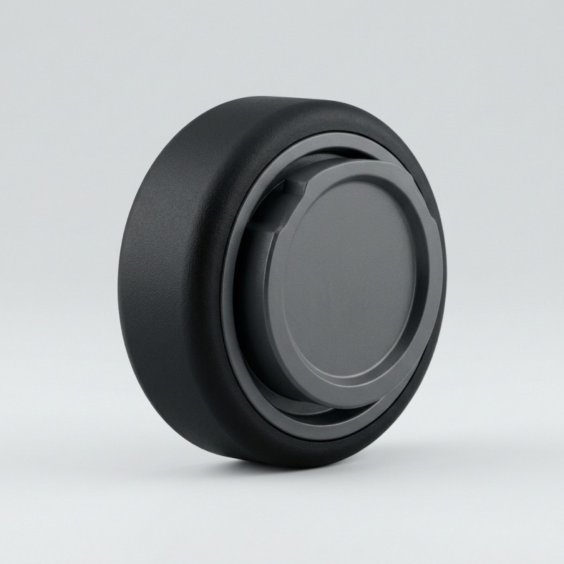
An LSR overmolded control knob can experience silicone grip rotation when the interface between the flexible silicone layer and rigid plastic core cannot transfer the operating torque required by the application. Preventing unwanted movement requires more than selecting a soft or textured silicone surface. Engineers should review the torque load path, silicone coverage, substrate geometry, bonding compatibility, mechanical retention, mold positioning and final assembly requirements before tooling. The finished knob should then be evaluated using the customer's actual operating conditions and acceptance criteria.
Why Can the Silicone Grip Rotate on a Plastic Control Knob?
An industrial control knob commonly combines a rigid plastic core with an LSR overmolded silicone grip surface. The rigid core provides the mounting structure, while the silicone layer forms the intended contact surface for the operator.
SiliconePlus offers a custom LSR overmolded industrial control knob developed around customer drawings or samples.
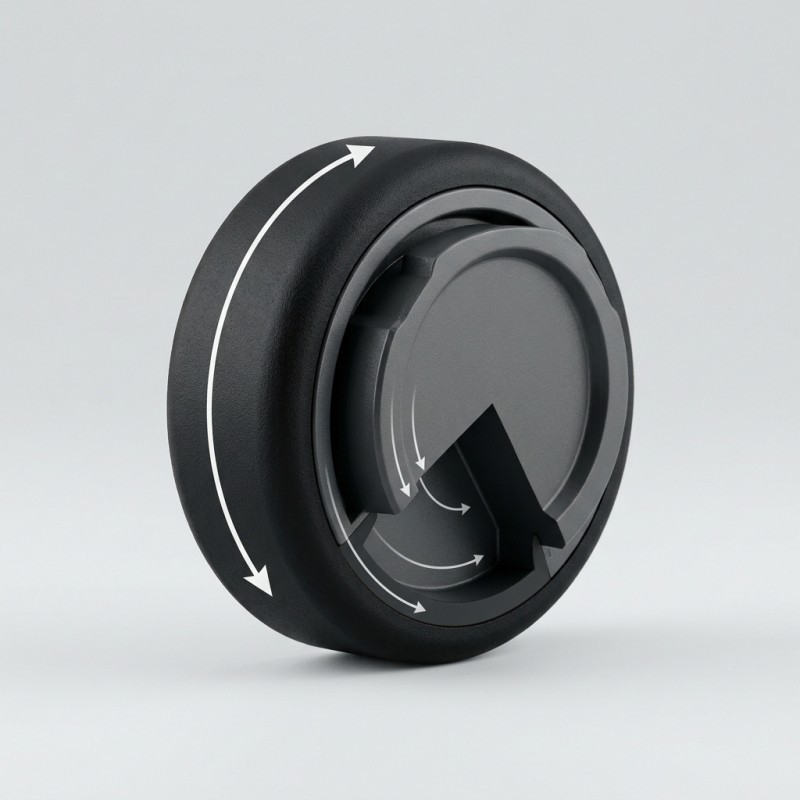
During operation, the user applies force to the outer grip. That force must pass through the silicone-to-plastic interface and reach the rigid core and its mounting connection.
If the interface cannot transfer the required torque, the silicone may move relative to the plastic core. The symptom may appear as a shifted grip position, inconsistent alignment or visible movement at the material boundary.
This is different from a knob that rotates normally on its equipment shaft because of an incorrect shaft fit. The engineering review must distinguish movement between the silicone and plastic core from movement between the complete knob and the equipment shaft.
Before tooling, define which interface is expected to transmit the operating torque and which surfaces are responsible for mounting and orientation.
Understand the Torque Load Path Before Changing the Grip Design
A control knob should be reviewed as a connected mechanical assembly rather than as a silicone surface placed on a plastic part.
The operating load generally passes through several interfaces:
1. The operator applies force to the silicone grip surface.
2. The silicone layer transfers the applied force to the plastic core.
3. The rigid core transfers the load toward the mounting interface.
4. The mounting interface transfers the operating torque to the equipment shaft or mating mechanism.
A problem at any interface can create movement that may be incorrectly attributed to the silicone material.
For example, a loose shaft connection may allow the complete knob to rotate or shift on the equipment. By contrast, a weak or unsuitable silicone-to-plastic interface may allow the grip layer to move while the plastic core remains correctly mounted.
The first step in failure analysis is therefore to identify the actual movement location.
The drawing should distinguish the silicone grip boundary, plastic core, shaft bore or mounting feature, and any orientation feature required by the equipment.
| Interface | Function | What to verify |
Operator to silicone | Applies operating force | Grip area and intended hand contact |
| Silicone to plastic core | Transfers torque into the rigid substrate | Bonding and retention design |
| Plastic core to mounting interface | Transfers torque toward the shaft | Core geometry and mounting fit |
| Knob to equipment | Operates the intended mechanism | Assembly orientation and functional fit |
What Should Be Reviewed at the Silicone-to-Plastic Interface?
The silicone-to-plastic interface is the main area to review when the grip layer moves independently of the rigid core.
The first consideration is the actual plastic grade. Different engineering plastics can have different surface characteristics, additives, reinforcement content and molding behavior. A silicone grade that works with one substrate should not automatically be assumed to work with another.
The project team should confirm:
- The exact plastic material and grade.
- Whether the plastic contains fillers or reinforcement.
- The condition of the surface entering the LSR process.
- Whether a self-bonding LSR system, primer or another approved bonding approach is being considered.
- Whether the design requires additional mechanical retention.
- Whether the substrate supplier or material grade may change during production.
Silicone-to-plastic bonding must be evaluated using the actual substrate and selected LSR material. Material names alone do not establish the bonding result.
For broader guidance on LSR overmolding mechanical retention, review how chemical bonding and physical locking address different interface risks.
| Review item | Engineering question | Potential concern |
Plastic grade | Is the exact substrate specified? | Bonding assumptions may not match the real material |
Surface condition | Is the incoming surface controlled? | Contamination or surface variation |
Bonding method | Is the selected method validated? | Inconsistent interface performance |
| Silicone coverage | Is the grip area clearly defined? | Unintended exposed or covered areas |
| Retention geometry | Does the structure match the load direction? | Relative movement under operation |
| Supplier change | Are material changes controlled? | Different substrate behavior between lots |
How Can the Interface Geometry Help Resist Relative Rotation?
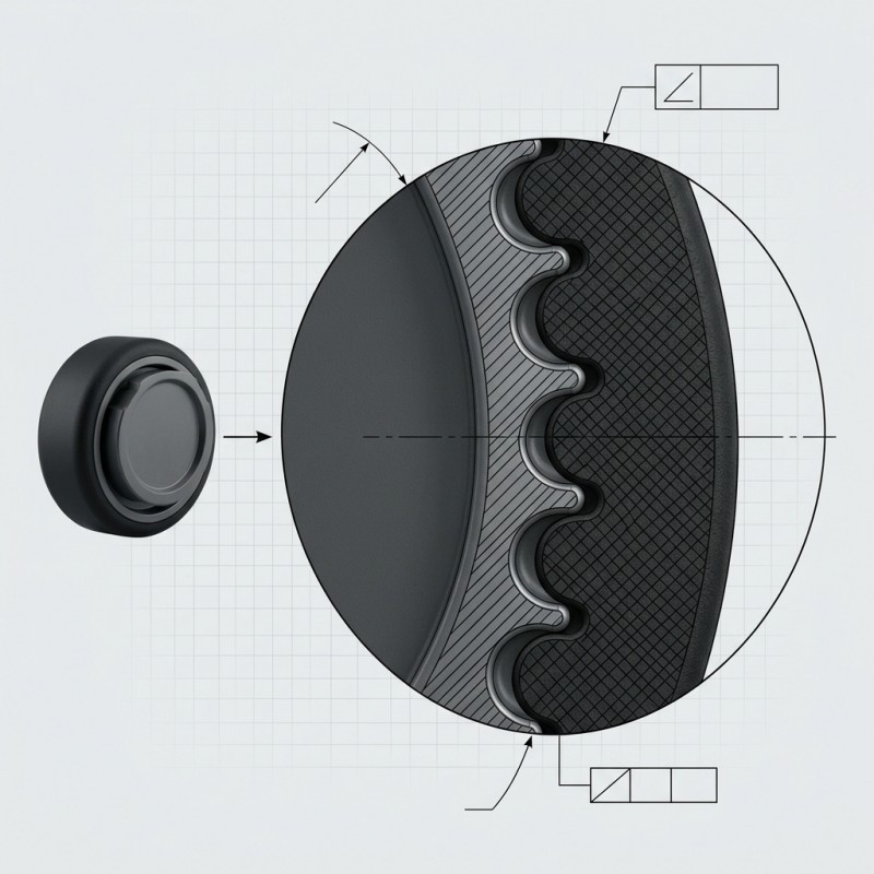
The interface geometry should be reviewed according to the direction in which the operating force enters the silicone grip.
A broad, flat interface may be straightforward to manufacture, but its performance depends on the selected material combination, surface condition, bonding process and actual load.
Where additional physical resistance to relative movement is required, the design team may evaluate suitable geometry that transfers load through more than a flat interface.
Possible concepts include:
- Circumferential or local grooves.
- Ribs or keyed interface features.
- Controlled undercuts.
- Through-holes or slots where the core design permits them.
- Silicone wraparound features around suitable plastic geometry.
These are design concepts, not a recommendation to add every feature to every knob.
A retention feature should be placed where it contributes to the real load path. Its dimensions must also remain compatible with silicone flow, insert strength, mold shut-off, venting and demolding.
For example, a feature that resists axial pull may not provide the same resistance to rotational movement. The geometry should be reviewed against the actual direction of torque rather than selected only because it is easy to add to a CAD model.
Sharp corners, thin silicone sections or poorly supported retention features may create new risks such as incomplete filling or tearing during demolding.
The final design should be reviewed with the silicone mold design capabilities of the manufacturing process in mind.
| Interface concept | Possible role | Design review |
| Flat bonded interface | Transfers load through the validated material interface | Bonding compatibility and surface control |
Circumferential groove | Adds a defined retention path | Filling, venting and local silicone thickness |
Keyed or ribbed interface | Provides geometric resistance to relative movement | Load direction and mold feasibility |
| Through-hole or slot | Allows silicone to form a physical connection through the core | Hole filling, trapped air and core strength |
| Edge wraparound | Extends the silicone interface around a suitable edge | Demolding and edge-tear risk |
Why Must the Shaft Interface Be Reviewed Separately?
A control knob has at least two different engineering interfaces: the silicone-to-plastic grip interface and the plastic-core-to-shaft mounting interface.
These interfaces should not be treated as one problem.
The shaft interface may use a bore, keyed profile, flat, spline or another geometry specified by the customer's equipment design. The actual arrangement must be confirmed from the drawing or physical sample.
If the shaft connection is loose, the complete knob may rotate or move relative to the equipment even when the silicone is firmly attached to the plastic core.
If the silicone layer moves while the core remains fixed, the investigation should focus on the overmolding interface and its ability to transmit the required torque.
The RFQ should therefore identify:
- The shaft or mating-part geometry.
- The required mounting orientation.
- The critical fit dimensions.
- Any key, flat or anti-rotation feature.
- The expected operating direction.
- The required inspection and assembly checks.
The silicone coverage must also remain clear of functional mounting surfaces unless the design explicitly requires otherwise.
For the broader manufacturing process, liquid silicone injection molding should be reviewed together with the actual insert, mold and assembly requirements.
How Should the Mold Control Insert Position and Silicone Coverage?
Even a suitable interface design can become inconsistent if the plastic core is not located correctly during molding.
Insert movement during mold closing or injection may change the silicone thickness, grip coverage boundary or position of a retention feature.
For a control knob, the mold review should consider:
- Stable locating references on the plastic core.
- Repeatable insert loading orientation.
- Support beneath thin or flexible substrate areas.
- The position of the silicone coverage boundary.
- The location of the mold parting line.
- Gate and venting feasibility.
- Demolding direction and possible undercuts.
- Protection of the shaft bore and other functional mounting surfaces.
The mold should reproduce the approved geometry without allowing silicone to enter areas that must remain exposed.
Insert positioning should also be considered during inspection. If the grip is not concentric or its boundary is shifted, the cause may involve insert location, substrate variation or tooling rather than the silicone material itself.

How Should Silicone Grip Rotation Be Evaluated Before Mass Production?
A visual inspection alone cannot confirm whether the silicone grip can transfer the operating torque required by the application.
The customer and manufacturer should define an evaluation method based on the real knob assembly and operating conditions.
A project-specific validation plan may include:
1. Dimensional inspection of the plastic core and molded grip.
2. Visual inspection of the silicone-to-plastic boundary.
3. Assembly inspection using the specified shaft or mating component.
4. A controlled torque test in the intended operating direction.
5. Inspection for relative movement between the silicone layer and plastic core.
6. Repeated operation where the application requires it.
7. Inspection after any specified environmental or aging exposure.
8. Pilot-production checks across representative parts and mold cavities.
The test fixture should distinguish movement at the silicone-to-plastic interface from movement at the shaft connection.
The customer should define the required torque, loading direction, test speed, cycle count, environmental conditions and acceptance limits. These values must not be assumed from a generic control-knob design.
The inspection method should also record where failure occurs. Silicone separation, plastic-core deformation and shaft-fit movement are different failure modes and require different corrective actions.
| Validation item | What to evaluate | Record |
Dimensional inspection | Grip geometry and mounting dimensions | Measurement results |
Visual inspection | Interface boundary, flash and visible separation | Inspection findings |
Assembly check | Fit with the specified shaft or mating component | Fit and orientation result |
Torque evaluation | Relative movement under the defined load | Applied condition and observed movement |
| Repeated operation | Stability under the customer's specified cycles | Before-and-after condition |
| Environmental exposure | Interface condition after required exposure | Test condition and inspection result |
| Pilot production | Repeatability across representative parts | Cavity and batch comparison |
What Should Buyers Include in an RFQ for an LSR Overmolded Control Knob?
A complete RFQ helps the manufacturer evaluate the plastic core, silicone grip, mounting interface and required operating function as one component.
For a custom LSR overmolded control knob, buyers should provide as much of the following information as possible:
- 2D drawing and 3D CAD model.
- Plastic core material and grade.
- Silicone material or functional requirements.
- Silicone coverage map.
- Grip texture and appearance reference.
- Shaft bore or mounting-interface drawing.
- Required orientation or anti-rotation features.
- Expected operating direction and torque requirement.
- Areas that must remain free of silicone.
- Required dimensional and visual acceptance criteria.
- Assembly drawing or representative mating component.
- Required functional and environmental validation.
- Prototype quantity and estimated production volume.
If the current design has already experienced silicone grip rotation, provide photos or samples showing the movement location. Explain whether the plastic core remains fixed while the silicone moves, or whether the complete knob moves on the shaft.
This distinction helps the engineering team focus on the correct interface before tooling changes are proposed.
A physical sample is useful when the existing mounting fit, grip geometry or failure location is difficult to communicate through drawings alone.
Information | Why it matters |
2D drawing and 3D model | Defines the complete component geometry |
Plastic grade | Supports substrate and bonding review |
Silicone requirements | Defines the intended grip material |
Silicone coverage map | Identifies covered and exposed areas |
| Shaft interface | Separates mounting fit from grip retention |
Operating torque requirement | Defines the load that the interface must transmit |
| Failure photos or samples | Helps identify the actual movement location |
| Inspection criteria | Establishes sample approval requirements |
| Estimated quantity | Supports tooling and production planning |
How SiliconePlus Supports Custom LSR Overmolded Control Knob Projects
SiliconePlus supports custom silicone overmolding projects involving rigid plastic inserts and application-specific silicone structures.
For industrial control knob projects, the engineering discussion can cover:
- Plastic core and silicone material review.
- Grip coverage and texture definition.
- Silicone-to-plastic interface evaluation.
- Mechanical retention feasibility.
- Shaft and mounting-interface review.
- Insert positioning and mold support.
- Mold parting-line and demolding considerations.
- Sampling and dimensional inspection.
- Project-specific functional validation.
The final material combination, interface design, operating torque requirement and inspection criteria should be confirmed for the customer's actual knob and equipment.
SiliconePlus provides drawing-based DFM review, tooling development, sampling and OEM manufacturing support for custom LSR overmolded components.
Frequently Asked Questions
Why does a silicone grip rotate on a plastic control knob?
Relative movement may occur when the silicone-to-plastic interface cannot transfer the required operating torque. Material compatibility, surface condition, bonding method, interface geometry and mechanical retention should be reviewed.
Does a textured silicone surface prevent rotation on the plastic core?
Not by itself. Surface texture may affect the operator's grip, but it does not automatically create a reliable torque-transfer connection between the silicone layer and the plastic core.
Can mechanical retention help prevent silicone grip rotation?
It may help when the selected retention geometry matches the load direction. Grooves, ribs, keyed features, slots or wraparound structures should be reviewed for filling, venting, insert strength and demolding feasibility.
Is silicone-to-plastic bonding the same as shaft retention?
No. Silicone-to-plastic bonding connects the grip layer to the rigid core. The shaft interface connects the complete knob to the equipment. Each interface needs its own dimensions and acceptance criteria.
How can a manufacturer verify whether the silicone grip is rotating?
A controlled evaluation should observe the silicone layer and plastic core separately while applying the customer's defined operating load. The test fixture must avoid confusing grip movement with shaft-fit movement.
What information is needed to develop a custom overmolded control knob?
Provide 2D and 3D drawings, plastic material, silicone requirements, grip coverage, shaft interface, operating torque requirement, assembly details and inspection criteria. A physical sample can help clarify the existing structure.
Conclusion
An LSR overmolded control knob must transfer operating torque through the silicone grip and rigid plastic core without unwanted relative movement.
A reliable design starts by distinguishing the silicone-to-plastic interface from the plastic-core-to-shaft mounting interface. Engineers should then review the actual load path, material compatibility, interface geometry, mechanical retention, insert positioning and mold feasibility.
The finished component should be evaluated using the customer's defined operating torque, assembly conditions and acceptance criteria. A visually acceptable silicone surface alone does not prove that the interface can meet the required operating function.
For OEM buyers, defining the load direction and providing the complete knob assembly before tooling can help reduce design ambiguity and improve the quality of the engineering review.
Discuss Your Custom LSR Overmolded Control Knob Project
Are you developing an industrial control knob with a rigid plastic core and an LSR overmolded silicone grip?
Send SiliconePlus your 2D drawing, 3D model, plastic material, grip coverage, shaft interface and operating torque requirements. Our team can review the proposed structure and discuss tooling, sampling and manufacturing feasibility.
Contact SiliconePlus to discuss your custom silicone overmolding project.
Custom LSR overmolding should be designed around the complete component and its real operating requirements—not only the appearance of the silicone grip.