Can an LSR Seal Bridge a Plastic-to-Metal Joint Without Leaking?
- Share
- publisher
- SiliconePlus Engineering Team
- Issue Time
- Oct 20,2026
Summary
Can a molded LSR seal remain leak-tight where a metal insert meets a plastic housing? The visible silicone bead may be continuous while a hidden plastic-to-metal gap bypasses the intended sealing path. This engineering guide explains interface mapping, feasible sealing architectures, DFM controls, diagnostic testing and the information buyers should provide before tooling.
Answer Excerpt
An LSR overmolded seal can potentially cross a plastic-to-metal joint, but a continuous silicone surface does not automatically make the underlying joint leak-tight. Fluid may travel through a connected gap between the metal insert and plastic frame, bypassing the molded silicone sealing lip. A reliable design should identify every potential fluid path, determine where the metal-to-plastic interface begins and ends, select a suitable sealing architecture, and validate both the overmolded interface and the final assembled housing under the actual operating conditions.
Why Can a Plastic-Metal Housing Leak Beneath an Intact LSR Seal?
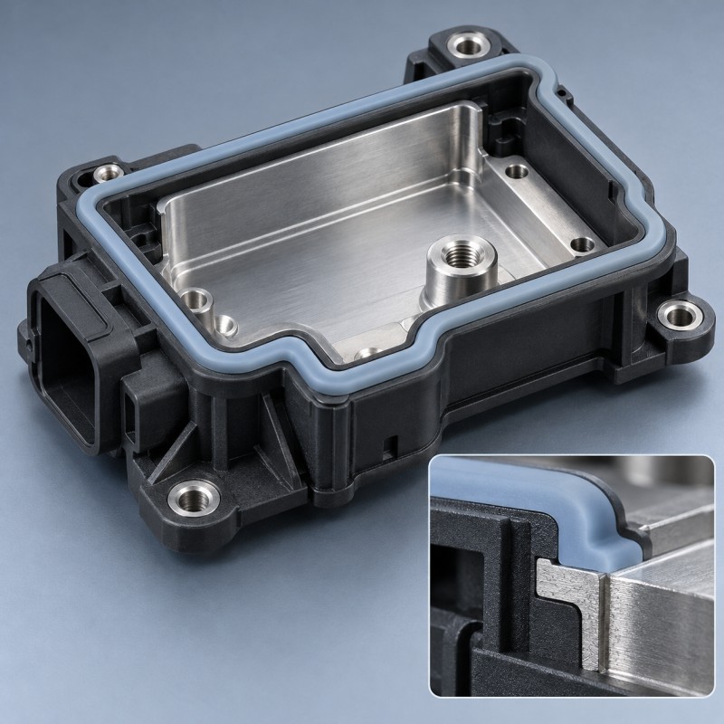
An integrated silicone seal may appear continuous around an engineering-plastic housing even when the underlying carrier contains more than one material.
Consider a component consisting of:
- A rigid engineering-plastic frame.
- A metal insert or mounting feature integrated into the frame.
- A localized liquid silicone rubber sealing structure.
- A mating cover, flange or other assembly component.
The silicone may be formed directly onto designated areas of the rigid carrier to create an integrated sealing feature.
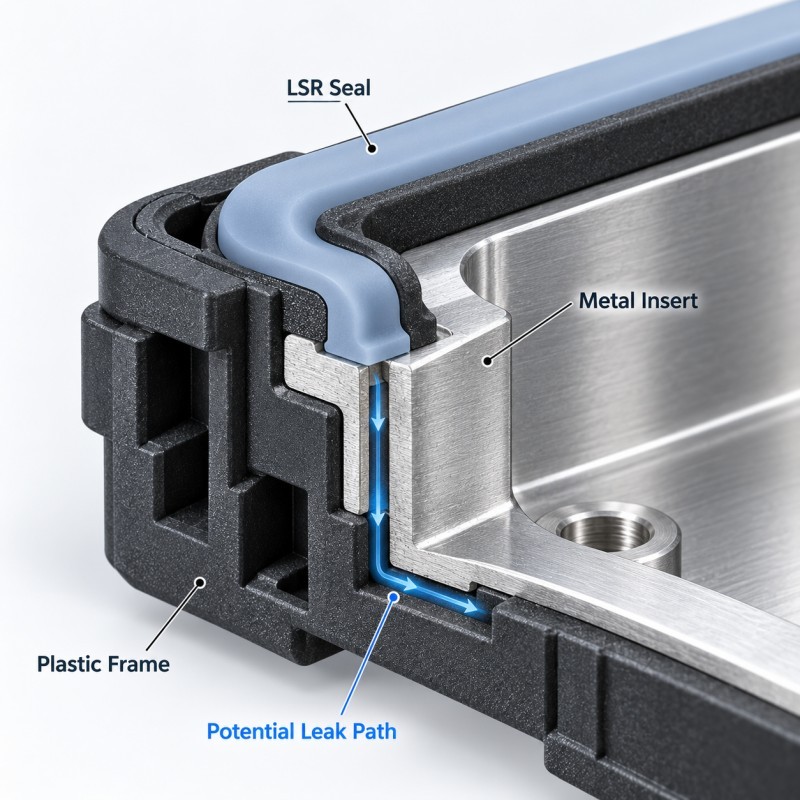
However, the metal and plastic may meet at a separate internal interface.
If that interface is connected to both a fluid-exposed region and the protected side of the assembly, it may provide an alternative path for moisture or coolant.
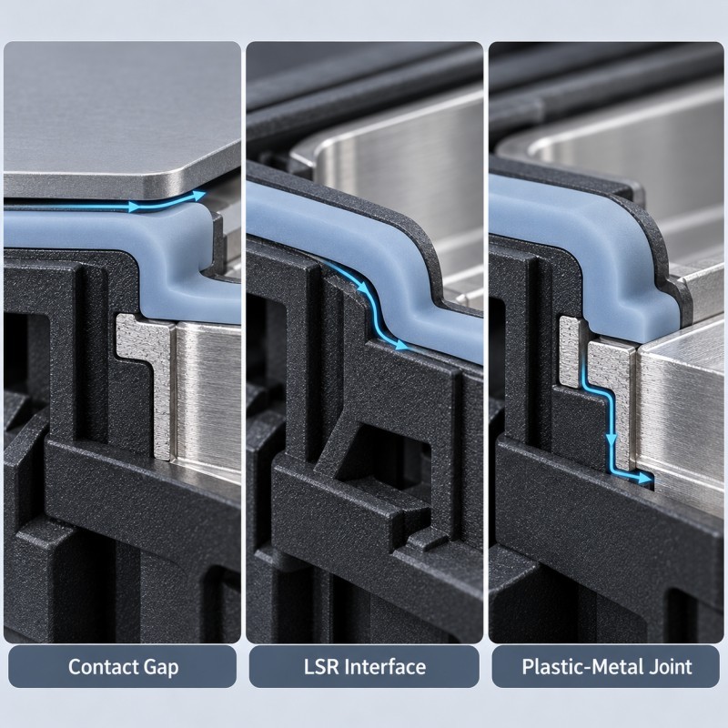
This distinction creates three different sealing questions:
First, does the silicone seal against the mating component?
The molded sealing lip must make adequate contact with its intended mating surface under the specified assembly conditions.
Second, is the silicone-to-carrier interface suitable?
The LSR must remain correctly positioned and retained on the designated plastic or metal substrate.
Third, is the plastic-to-metal interface itself sealed?
The joint between the two rigid materials may require its own sealing strategy, independent of the outer silicone profile.
A successful result at the first two interfaces does not automatically answer the third question.
For a relevant custom component architecture, see the custom metal insert LSR overmolded sealing housing. Its specified construction combines an engineering-plastic frame, metal insert and localized silicone sealing feature.
SiliconePlus also provides metal with silicone overmolding manufacturing for drawing-based rigid-soft components requiring selected sealing, insulation or protective regions.
These references describe a real manufacturing direction, but the exact leakage boundary of any customer project must be established from its assembly drawing and validated test requirements.
The most important design step is to map the complete fluid path before choosing the silicone geometry.
Which Interfaces Must Be Evaluated in a Three-Material LSR Overmolding Design?
A plastic-metal-LSR component should not be evaluated as one uniform bonding surface.
At least four interface groups may need review.
1. The silicone-to-plastic interface
This is the area where the molded LSR directly contacts the engineering-plastic substrate.
Its behavior depends on the selected plastic grade, silicone formulation, surface condition, part geometry and bonding or retention method.
The interface may require an approved chemical bonding system, mechanical retention or a suitable combination.
2. The silicone-to-metal interface
The metal insert may be exposed, plated, coated or partially embedded inside the plastic.
If the LSR directly contacts metal, the actual surface condition must be included in the DFM review.
Machining oil, oxidation, plating changes and handling contamination can affect the interface.
The guide to metal insert preparation before LSR overmolding explains why the approved metal surface should remain consistent from sampling through production.
3. The plastic-to-metal interface
This interface already exists before the LSR sealing feature is evaluated.
Depending on the manufacturing route, it may have been created by plastic insert molding, mechanical assembly, press fitting or another joining method.
Its sealing performance cannot be inferred from the fact that the surrounding plastic looks closely fitted to the metal.
A nominal zero-clearance CAD model does not necessarily mean that the production joint contains no connected microgap.
4. The silicone-to-mating-component interface
This is the final contact region created when the housing, cover or fitting is assembled.
It may be an axially compressed sealing lip or another project-specific geometry.
Its performance depends on the final mating gap, substrate stiffness, surface condition, compression and environmental exposure.
These interfaces are mechanically connected but not interchangeable.
A part can have excellent silicone retention while allowing fluid to bypass the silicone through another region of the carrier.
Likewise, an internally sealed plastic-metal joint does not compensate for inadequate compression at the outer sealing lip.
The assembly drawing should define which interface is responsible for blocking each possible fluid path.
Should the LSR Seal Cross the Plastic-Metal Boundary or Stay on One Substrate?
There is no universal requirement to place an LSR sealing bead directly across a plastic-to-metal joint.
The most suitable architecture depends on where the fluid is located, how the rigid carrier is manufactured, and which interfaces can be qualified.
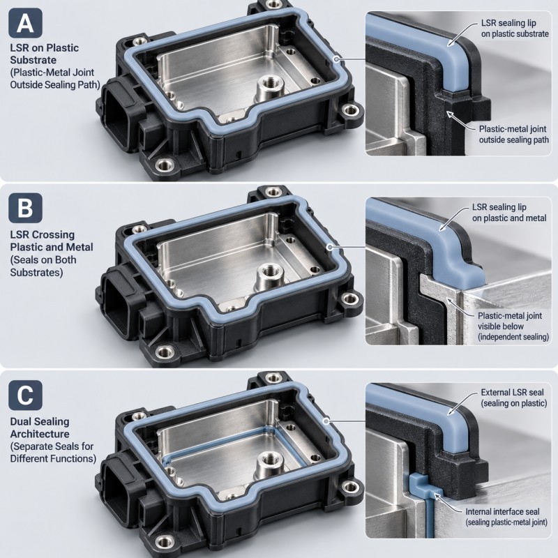
Three design approaches should be compared.
Route A: Keep the primary silicone sealing path on one continuous substrate.
Where geometry allows, the LSR sealing feature can be positioned entirely on a suitable, uninterrupted plastic or metal region.
The plastic-to-metal joint can then be located outside the protected fluid path.
This approach may simplify interface qualification because the silicone does not need to transition repeatedly between two different rigid bonding surfaces.
It is not sufficient, however, if fluid can reach the plastic-to-metal joint through another path.
Route B: Use LSR across the transition with a qualified underlying joint.
Some components require the sealing feature to pass from plastic onto metal.
In this situation, both silicone interfaces and the rigid plastic-metal connection must be evaluated.
The molded silicone should not be assumed to penetrate and seal an inaccessible internal gap.
If the rigid joint is exposed to fluid, it may need a separate qualified sealing mechanism.
Route C: Redesign the carrier or add an independent joint barrier.
If the plastic-to-metal connection cannot provide the required sealing function, the engineering team may need to revise the carrier geometry, joining method or internal sealing arrangement.
The independent barrier must be compatible with the materials, manufacturing temperatures, fluids and final assembly.
This is a system-design decision rather than a simple instruction to increase the LSR wall thickness.
The preferred route is the architecture that provides a clearly defined, manufacturable and testable barrier against every specified leakage path.
Plastic-Metal-LSR Sealing Architecture Comparison
| Design Route | Silicone Location | Primary Advantage | Main Validation Concern |
| A. Single-substrate seal | LSR remains on one continuous plastic or metal land | More clearly defined primary bonding surface | Separate plastic-metal joint must not bypass sealing boundary |
| B. Cross-boundary LSR seal | LSR transitions across plastic and metal | Supports certain compact integrated geometries | Different interfaces and underlying rigid joint need validation |
| C. Revised joint or independent barrier | LSR works alongside a separate joint-sealing structure | Assigns different leakage paths to defined barriers | Added joining, material, assembly and qualification requirements |
How Should the Plastic-to-Metal Transition Be Designed Before LSR Tooling?
The plastic-to-metal transition should be reviewed as an engineering feature with its own geometry, tolerance and manufacturing history.
The following controls are especially important.
Define both rigid materials precisely.
The drawing should identify the exact engineering-plastic grade and metal alloy.
If the metal has plating or coating, that condition should also be specified.
The materials may respond differently to thermal exposure, surface preparation and mechanical loading.
Identify the real transition line.
Do not rely only on the cosmetic boundary visible on the outer face.
A metal insert may extend beneath the plastic or contain undercuts, holes and other retention structures.
The actual internal joint geometry can differ substantially from the visible surface line.
Check whether the rigid joint forms a connected passage.
If the plastic-metal connection lies between a wet region and a dry region, engineers should evaluate whether a continuous path exists along the interface.
Local contact pressure, insert retention and nominal zero-clearance geometry should not be treated as proof of fluid tightness.
Protect functional metal and plastic areas.
Metal threads, installation holes, locating faces, electrical contact areas, mating surfaces and other required openings should remain silicone-free where specified.
A sealing feature should not interfere with the structural function of the rigid carrier.
Control the support beneath the silicone bead.
A seal that crosses a step, recess or poorly supported area may deform differently from one formed on a smooth, stable substrate.
The final assembly could create unequal compression or localized deformation.
Evaluate the bonding system separately for each substrate.
A silicone formulation suitable for one engineering plastic is not automatically suitable for the exposed metal insert.
The discussion of how LSR overmolding bonds to plastic and metal inserts provides additional background on material compatibility, surface condition and retention.
Review differential movement.
The plastic, metal and silicone may expand, contract or deform differently during molding, assembly and environmental exposure.
The relevant movement depends on the actual geometry and temperature history.
Any resulting stress at the boundary should be assessed for its effect on silicone retention, seal compression and the underlying rigid joint.
Define measurable acceptance criteria.
The drawing and inspection plan should identify:
- Primary sealing contact surfaces.
- Permitted silicone coverage boundaries.
- Metal-to-plastic joint geometry.
- Critical part dimensions and positional datums.
- Acceptable interface condition.
- Areas requiring section inspection.
- Assembly-level leakage requirements.
The objective is not to eliminate every visible material transition.
It is to ensure that each transition has a clear structural role and a testable sealing responsibility.
Which LSR Molding Controls Matter at the Material Transition?
A viable sealing architecture still requires a repeatable molding process.
For a hybrid plastic-metal carrier, process development should consider the condition of the complete rigid insert before LSR injection.
Insert preparation
Confirm that the plastic frame and metal insert have been manufactured and assembled according to the approved specification.
Inspect exposed metal condition, plastic damage, deformation and visible joint irregularities.
If cleaning or surface treatment is required for a selected bonding system, use a defined and compatible process.
Insert positioning
The complete carrier must be held consistently during tool loading and closing.
A locating scheme should reference stable structural datums rather than a flexible or poorly controlled interface.
If the metal insert or plastic frame changes position during molding, the silicone coverage and final seal geometry may vary.
Mold shut-off
The mold must prevent LSR from entering threads, precision locating features, fluid passages, mounting holes and other no-silicone regions.
Special attention is required near changes in insert height or material boundary.
A local step or poorly controlled dimensional variation can create a clearance that allows silicone flash.
Flow and venting
The gate and venting design should fill the required silicone cavity without displacing the carrier or leaving incomplete sections.
The final flow-front meeting location should be reviewed where it falls near a critical sealing area.
Curing exposure
The plastic grade, metal insert, any joining materials and surface treatments must tolerate the actual LSR molding process.
The fact that the metal itself tolerates the process does not prove that the complete rigid assembly is dimensionally stable.
Demolding and handling
Removing the finished component must not peel the silicone from an edge or distort the rigid joint.
A component with multiple substrates may have different local stiffness and support conditions.
Process repeatability
Sampling should establish repeatable coverage, insert location, visible interface condition and final dimensions.
Representative production lots should include approved variation in incoming plastic frames and metal inserts.
For additional background on suitable plastic substrates, see plastic with silicone overmolding manufacturing.
The process should be accepted only after the chosen structure has been evaluated under the relevant project conditions.
How Can Engineers Distinguish Seal Failure From a Hidden Plastic-Metal Leak?
Failure investigation should begin by separating the silicone sealing surface from the internal rigid-material interface.
Both may be close to each other, but they require different corrective actions.
Step 1: Establish the baseline assembly condition.
Record the plastic material, metal insert specification, silicone material, assembly drawing, critical dimensions and approved molding process.
Confirm whether the tested component represents the intended final assembly.
Step 2: Inspect the primary sealing contact.
Check the silicone bead for incomplete filling, tears, damage, local distortion and contamination.
Inspect the mating surface and verify whether the rigid structure reaches the intended final assembly position.
For designs using rigid stops, the related compression stop design for LSR overmolded seals explains how the stop geometry affects the available silicone compression.
Step 3: Inspect the silicone-to-carrier boundary.
Look for edge lifting, incomplete coverage or local separation on plastic and metal surfaces.
Where necessary, use a controlled section through the relevant interface.
Step 4: Examine the underlying plastic-to-metal joint.
If the silicone bead appears intact, the investigation should not stop.
Assess whether fluid could move along an internal gap between metal and plastic and emerge beyond the protected boundary.
The risk depends on the actual rigid joint, not merely the visual position of the silicone.
Step 5: Use controlled test configurations where practical.
A comparison between appropriate test configurations may help isolate the primary sealing lip from the underlying rigid joint.
Any temporary blocking, tracer or fixture modification must be documented because it can change the original leakage path.
These investigations should be planned by the customer's engineering and validation team.
Step 6: Identify the correct corrective action.
If the primary silicone contact fails, the solution may involve seal geometry, assembly gap, material selection or molding consistency.
If the silicone-to-carrier interface fails, bonding or retention may need revision.
If the underlying plastic-metal joint leaks, increasing the outer silicone height is not necessarily an effective solution.
The rigid joint or complete sealing architecture may need to be redesigned.
A useful failure report should identify the suspected leakage path, observed evidence, limitations of the test, corrective action and required revalidation.
Hybrid Housing LSR Overmolding Validation Matrix
| Validation Item | What to Check | Main Risk |
Plastic and metal specifications | Exact grades, finishes and joining construction | Incorrect material assumptions |
Rigid joint continuity | Possible paths between wet and protected sides | Hidden bypass leakage |
Silicone material compatibility | LSR interaction with each exposed substrate | Inadequate interface suitability |
Insert positioning | Metal and plastic location during molding | Shifted silicone sealing geometry |
Mold shut-off | Functional openings and critical edges | Flash or blocked features |
| Seal compression | Final assembly gap and contact path | Under- or over-compression |
Interface inspection | Silicone edges and representative sections | Separation or incomplete coverage |
Joint-specific leakage assessment | Underlying rigid plastic-metal connection | Leakage below an intact silicone bead |
| Full assembly test | Project-defined fluid, temperature, pressure and duration | Unqualified finished-product sealing |
Environmental and mechanical conditioning | Required aging, thermal or load exposure | Changes after initial sample acceptance |
| Pilot production | Multiple inserts, cavities or approved production lots | Process variation |
Frequently Asked Questions
Can LSR seal both plastic and metal in one overmolded component?
It may be possible when the exact silicone formulation, plastic material, metal surface, joint geometry and molding conditions are suitable. However, bonding to both substrates does not automatically prove that a separate plastic-to-metal interface is fluid-tight. Each relevant sealing boundary must be evaluated.
Does a continuous silicone bead guarantee a waterproof plastic-metal housing?
No. A continuous visible bead may provide the intended external contact seal while an underlying rigid-material joint still contains a connected leakage path. The full assembly must be evaluated against the specified ingress or fluid-sealing requirement.
Should the silicone sealing lip be placed directly across the plastic-metal joint?
Not necessarily. Where possible, a continuous sealing land on one qualified substrate may simplify the design. If the seal must cross the joint, both silicone interfaces and the underlying connection should be evaluated. The final choice depends on the actual carrier geometry and fluid path.
Can a thicker LSR layer stop leakage through the rigid joint?
Not reliably by itself. Additional silicone thickness may change the external geometry but does not necessarily seal an internal path between metal and plastic. The leakage source should be identified before deciding whether the solution requires a revised silicone profile, joint design or independent barrier.
What drawings are needed for a plastic-metal LSR sealing project?
Provide the complete 2D and 3D assembly drawings, plastic and metal specifications, insert joining method, silicone coverage map, critical no-silicone zones, mating component geometry, intended fluid exposure, pressure and temperature conditions, validation criteria and estimated production quantity. Physical samples can support the DFM review.
Conclusion
A plastic-metal-LSR sealing component contains more potential interfaces than its external appearance suggests.
The silicone may form a continuous molded feature, but the underlying rigid joint must still be evaluated as a possible fluid path.
The engineering review should distinguish the silicone-to-plastic interface, silicone-to-metal interface, plastic-to-metal joint and final sealing contact with the mating assembly.
A practical design process starts by mapping the complete fluid path, selecting an appropriate sealing architecture, verifying the materials and insert structure, and testing the actual assembled product.
When the rigid-material joint is part of the protected boundary, its sealing responsibility must be defined explicitly.
The best solution is not necessarily the largest silicone coverage area.
It is a controlled combination of materials, geometry, molding process and validation that addresses the real leakage paths without interfering with the component's electrical, mechanical or assembly functions.
Discuss Your Plastic-Metal LSR Overmolding Project With SiliconePlus
Are you developing a plastic-metal hybrid housing that requires an integrated silicone sealing feature?
SiliconePlus supports custom LSR overmolding projects involving engineering-plastic structures, metal inserts and localized silicone coverage.
For a project-specific DFM review, our team can discuss the proposed insert geometry, substrate specifications, silicone coverage boundaries, mold feasibility and inspection requirements.
To help evaluate your project, please prepare:
- Complete 2D or 3D part and assembly drawings.
- Engineering-plastic material and metal insert specifications.
- Plastic-to-metal joining method and relevant joint details.
- Required LSR sealing area and functional keep-out zones.
- Mating cover, flange or connector geometry.
- Intended fluid exposure and environmental conditions.
- Customer-defined leakage and durability acceptance criteria.
- Physical samples, where available.
- Prototype quantity and estimated production demand.
Please contact SiliconePlus to discuss your custom plastic-metal-LSR sealing component before tooling development.